diy solar

diy solar

Safety hazard w/ Growatt 5000ES (European version) when connected to American grid

I don't find the GroWatt name on the ca.gov site, but I do find "GoodWe Technologies Co., Ltd. GW5000A-ES [240V]"

That's because you didn't look far enough. :)

Look for " Shenzhen Growatt New Energy Technology Co., Ltd "
On the GroWatt site (.pdf) you linked I find "MIN5000TL-XH-US"
The GW's listed for Rule 21 are not the GW's most are using here. The reason? Those are grid tie interactive inverters for Rule 21, the inverters most of are using are standalone hybrid type and not subject to Rule 21. Which is why some members claim the GW's aren't approved for CA use but there is a difference with conforming to UL 1741 (TUV-us) for such an inverter. I'm not in CA and as such don't have to concern myself with this, but one member claimed he couldn't find any hybrid inverters for use in CA that were approved. That is not the case.

Technically, as long as the unit can't backfeed to grid, then it is Rule 21 compliant and UL1741.
 
Last edited:
That's because you didn't look far enough. :)

Look for " Shenzhen Growatt New Energy Technology Co., Ltd "

The GW's listed for Rule 21 are not the GW's most are using here. The reason? Those are grid tie interactive inverters for Rule 21, the inverters most of are using are standalone hybrid type and not subject to Rule 21. Which is why some members claim the GW's aren't approved for CA use but there is a difference with conforming to UL 1741 (TUV-us) for such an inverter. I'm not in CA and as such don't have to concern myself with this, but one member claimed he couldn't find any hybrid inverters for use in CA that were approved. That is not the case.

Technically, as long as the unit can't backfeed to grid, then it is Rule 21 compliant.

Technically (if the unit mixing grid power and PV power to output, like the batteryless inverters) it "could" backfeed.
Only a sensor measures the current going into the inverter ... and the inverter self limits based on that.
 
Technically (if the unit mixing grid power and PV power to output, like the batteryless inverters) it "could" backfeed.
Only a sensor measures the current going into the inverter ... and the inverter self limits based on that.

And then my concern would be, if utility line broke, would the inverter continue operating, maintaining AC voltage on the wire. Maybe even backfeed a small amount, below the "do not export" threshold it detects, but perhaps > 30 mA.

UL-1741 anti-islanding would serve to prevent that. So I think any inverter which adds power to a circuit simultaneously fed by grid needs a certain level of qualification to be safe.
 
And then my concern would be, if utility line broke, would the inverter continue operating, maintaining AC voltage on the wire. Maybe even backfeed a small amount, below the "do not export" threshold it detects, but perhaps > 30 mA.

No it will not :) The relays on the AC_in part disengage on a blackout.
So anti-islanding is working in these inverters too.

UL-1741 anti-islanding would serve to prevent that. So I think any inverter which adds power to a circuit simultaneously fed by grid needs a certain level of qualification to be safe.


If someone is very grouchy about it then AC_out (and direct grid) can be connected to an ATS (and its output to give power to the house).
Also a separate protective device can be added on AC_in side:
And so this is the second layer for anti-islanding protection :)
 
Last edited:
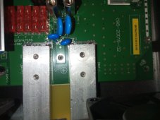
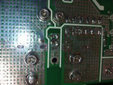
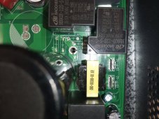
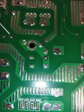
OK so I have opened up a clone 230v converter and investigated the bonding screw issue. I don't know how similar it is to an MPP unit or Growatt but at lease we have a clue to work from.
There are 2 (TWO) bonding/grounding/earthing screws, whatever we should call them and the bottom line is, REMOVING THE SCREWS WILL NOT RELIABLY REMOVE THE BOND TO GROUND.
The first screw is between the battery input terminals and connects some capacitors to the chassis of the unit.
IMG_20220116_121748_0.jpg
IMG_20220116_121807_1.jpg
The second screw is in the center of the board, as Ian has shown. On my clone unit it does absolutely nothing because 4 capacitors and a link are not fitted from the factory. If the link was fitted it would connect neutral to the case/ground on the output of the 230v connections.
IMG_20220116_121728_4.jpg
IMG_20220116_121829_8.jpg
The input 230v connections are floating and connected to nothing other that circuits. The ground input and output are connected together via wires and screws to the case.
 
I've asked everyone I've seen claiming insurance companies don't pay because you screwed something up if they can quote from their policy where it says that, still waiting for someone to find the language. Really wish people would stop with the insurance fear mongering and stick with just telling people what they are doing is a bad idea and why.
It's very obvious that you have never had this problem yourself.
One of the companies I worked for had some modifications done to the Electrical room without going through all the proper procedures. It was a small mod but the dam thing caused a fire in the room a few months later that created about $100K worth of damage to the room. The fire dept did their investigation and located where the fire started. Long and short was that we ended up repairing the room out of pocket while the insurance company denied paying the claim based on statements from one of the maintenance people to the fire dept that modifications had been done just months before. In the end they did pay us but it was only after about 6 months and a lawyer had become involved. Finding an Autotransformer and a 240V inverter in an electrical fire investigation is going to set off alarm bells.
 
OK so I have opened up a clone 230v converter and investigated the bonding screw issue. I don't know how similar it is to an MPP unit or Growatt but at lease we have a clue to work from.
There are 2 (TWO) bonding/grounding/earthing screws, whatever we should call them and the bottom line is, REMOVING THE SCREWS WILL NOT RELIABLY REMOVE THE BOND TO GROUND.
The first screw is between the battery input terminals and connects some capacitors to the chassis of the unit.
View attachment 79935
View attachment 79937
The second screw is in the center of the board, as Ian has shown. On my clone unit it does absolutely nothing because 4 capacitors and a link are not fitted from the factory. If the link was fitted it would connect neutral to the case/ground on the output of the 230v connections.
View attachment 79938
View attachment 79939
The input 230v connections are floating and connected to nothing other that circuits. The ground input and output are connected together via wires and screws to the case.
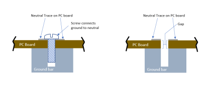
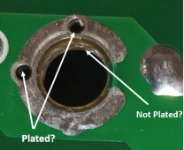
Are those through-hole traces? (Does the conducting trace line the hole that the screw goes into?) It looks like there is no through-hole trace in the picture.

If I am looking at the pictures correctly, the ground connection is a metal part behind the board and the Neutral connection is the top side trace on the board. The screw then 'bridges' the connection from the top to the bottom. As long as the hole does not have 'through hole' traces this would separate the ground from the neutral quite effectively and there would be little chance of flex in the board making any connection.

Edit: Added detail on the PC board breakdown voltage.
One might argue that the gap created by the PC board is too small, but it is actually quite large. The board itself probably has a breakdown voltage around 25KV/mm and the air has a breakdown voltage of 3kV/mm.

1642365607034.png
 
Last edited:
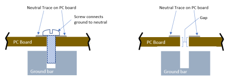
"Creepage and clearance", 0.062" thickness of typical PCB isn't much in terms of creepage. And rough drilled hole probably worse in that regard.
(Doesn't mean it will fail, i.e. short. But might not comply with standoff requirements depending on voltage.)
 
0.062" thickness of typical PCB isn't much in terms of creepage
Clearance
.062" = 1.575mm
1.575mm x 3000v/mm = 4.725KV
divide that by 4 to account for any flaws in the board and you still get over 1KV in breakdown voltage.

Creepage (I had not considered that before and it is a good point)
This will depend on the geometry of the setup, and without a better understanding of the physical design, I can only speculate.
1st let's assume the same .062 inches and that the board remains in contact with the ground bar(Like I drew above). In this case, if there is conductive pollution on the surface the design would be marginal. Since there are fans in the inverter, we have to assume there will be conductive pollution. (We have all seen the dust buildup on the inside of a PC)

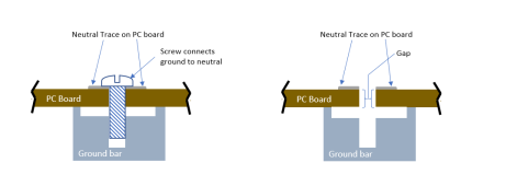
However, if the board does not contact the ground bar, creepage would be a nonissue. If they have the ground bar far enough under the PC board to accommodate a reasonable amount of flex without touching it would be sufficient. Other posters have commented that the board could flex to cause a problem so I will assume the ground bar does not normally touch the PC board. At that point, it becomes a question around what amount of flex of the board without touching is reasonable
1642371441634.png

Furthermore, they could design the geometry of the ground bar to minimize the issue.
1642370713746.png
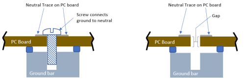
Finally, if they have insulating stand-offs they could pretty much eliminate any reasonable possibility of an issue.

1642371246221.png

I have no idea if the engineers did any of this or not. As I said, my comments on creepage are speculation. However, without more detail, I can't automatically say it is a bad design.
 
Last edited:
No, you can clearly see the via's do that
Is this what you mean?
1642373817540.png

If the smaller holes are through plated, then the metal the screw threads into to make contact needs to be physically separated from the board.
Is there a gap between the board and the metal the screw goes into?
 
Is this what you mean?
View attachment 79971

If the smaller holes are through plated, then the metal the screw threads into to make contact needs to be physically separated from the board.
Is there a gap between the board and the metal the screw goes into?
Yes those are the via's. The reason the mounting holes are not through plated is because the hole would fill with solder in the bath.
There is NO GAP between the board and the metal post the screw goes into. Without the screw the connection may or may not be made.
Hence why I commented on Ian's video that I do not like the screw removal method, it is not reliable. The wire link (JP2) needs to be cut.
I don't know if Growatt or MPP have this same arrangement, this is just what I found on my knock off unit that has blown up.
 
One picture, on component side, has ground symbol next to that screw.
Looks to me like it's purpose it to bond metal case to ground net in PCB, which might connect to ground wire through a terminal on the PCB.

Other picture by battery terminals is similarly labeled.

Is there such a screw between Neutral net of the PCB and case?
 
It's very obvious that you have never had this problem yourself.
One of the companies I worked for had some modifications done to the Electrical room without going through all the proper procedures. It was a small mod but the dam thing caused a fire in the room a few months later that created about $100K worth of damage to the room. The fire dept did their investigation and located where the fire started. Long and short was that we ended up repairing the room out of pocket while the insurance company denied paying the claim based on statements from one of the maintenance people to the fire dept that modifications had been done just months before. In the end they did pay us but it was only after about 6 months and a lawyer had become involved. Finding an Autotransformer and a 240V inverter in an electrical fire investigation is going to set off alarm bells.
You are talking commercial, I am talking residential. But thanks for confirming that even in your case the insurance company paid.
 
You are talking commercial, I am talking residential. But thanks for confirming that even in your case the insurance company paid.
Yes if you are valuable high premium customer who can afford to hire a good lawyer plus wait 6 months to be paid! My take was that the loss of our business and the escalating pressure was the only reason they gave in.
 
Hey everyone, I know this is a big issue that has a lot of people looking at Growatt products (and likely several other inverters as well). I'd like to step in to just clarify a few things:
1. The grounding screw is removed at Growatt for the units we sell. I can't speak for other providers but we discovered this issue at the beginning of our partnership with Growatt and it is OEM for inverters sold by SS to have this removed. This allows you to maintain your full warranty.
2. Based on this thread, we are going to do additional research into insulating and preventing accidental issues of the PCB touching the chassis or any other part of the inverter that would cause this issue to reoccur. We appreciate any feedback from users so we can make sure everyone feels safe using our products.
3. Safety is always our #1 priority. We understand the inherent dangers of working with electricity and always side with caution over sales or profit. That being said - we also want to stress the importance for DIYers to practice safe protocols when working with these units. Regardless of features and functions we add, there will always be the chance at hurting yourself or your property when you work on and around these units. NEVER work with a unit that is connected to a power source, NEVER open your unit while it is powered on or connected, and NEVER undertake any task that you are not 100% comfortable working on. Please do not risk your health or the safety of your property or loved ones under any circumstances.

I look forward to hearing any feedback and we will be updating everyone with additional information about this issue in the near future. If you have any worries or doubts about the product or safety, please heed caution as necessary.
 
Back
Top