


You are using an out of date browser. It may not display this or other websites correctly.
You should upgrade or use an alternative browser.
You should upgrade or use an alternative browser.
Sol-Ark 15K All in One Inverter Released.
- Thread starter robby
- Start date
Hedges
I See Electromagnetic Fields!
- Joined
- Mar 28, 2020
- Messages
- 20,819
I'd get SMA gear, but two Sunny Island and two Sunny Boys would be pushing $8-10k.
SMA gear for SolArk money.
Value for money is best if PV wattage is twice battery inverter wattage.
Each Sunny Island can pass through 56A to/from grid, 6.7kW, all on the 120V phase it is connected to.
If never backfeeding grid, each Sunny Island (6kw) can manage 12kW of GT PV, e.g. 2x 6.0 Sunny Boys.
You can make a system with a single Sunny Island plus an auto or isolation transformer making 120/240V split-phase.
You could have grid feed a main panel with one Sunny Boy, panel feeds Sunny Island and a protected loads panel with one Sunny Boy. In the event of grid failure, protected loads panel automatically supported with PV and battery. Switch and interlocked "generator" breaker on main panel (and turn off breaker feeding Sunny Island), now your whole house is backed up with 12kW of PV and 6kW of battery.
Some inverters with CT for export limit could be controlled while on-grid despite no frequency shift. I think SMA does this with a 3rd party meter, but also some internet connection I don't understand. Not sure if there is a gizmo you can have on-site that would read utility current and throttle the inverter. Also not sure that would be fast enough to limit relay current before Sunny Island reacts.
I plan on installing a 15K Solark later this summer. My current grid feed is direct from outdoor meter, to 200A main panel in basement. Can anyone suggest the best method to re-direct the main input from the main panel to the new sol-ark, then feed the main panel with the sol-ark, as it appears Sol-ark is recommending.
So far I have done some inquires about installing a main panel cut off switch, that I could then use to make the new connections... but no one appears to be interested in just doing that job.
I can't imagine it is more than a 1 day job from start to finish, anyone care to guess how much a move of the main feed from main panel to sol-ark 15K input then back to the main panel would cost?
THanks
Hedges
I See Electromagnetic Fields!
- Joined
- Mar 28, 2020
- Messages
- 20,819
200A main breaker is at the main panel, no breaker at the meter?
In that case, meter gets yanked so wires aren't live during the connection.
Does SolArk have a 200A pass-through relay built in? Does it have the ability to close that relay, leaving power to house on while the rest of SolArk gets removed and shipped back for repair?
If not, would be awfully nice to have some kind of bypass/transfer switch so the lights stay on when SolArk is down for the count. But, the amount of switch gear required to send 200A straight through vs. diverting through SolArk and back will cost serious $$$.
Just a fused 200A disconnect is available. Or a new meter box with built-in main breaker. Probably less expensive than the fused disconnect!
How about instead installing a new 400A main panel with 200A main breaker? That would allow up to 200A (or more) PV breaker without violating 120% rule. But I'm not aware of branch breaker larger than 125A for consumer panels. You could have 200A main breaker at meter, 125A breaker feeding SolArk feeding existing panel, 125A breaker bypassing SolArk to an interlocked 125A "generator" breaker on existing panel.
(Maybe 2/0 cables could tap off mounting screws of 200A main breaker on new panel, feeding into 200A main breaker of existing panel, but not sure that is considered proper. More likely, two sets of 2/0 cables from fused disconnect, one set to SolArk and one to main breaker of existing panel. Sol-Ark could feed interlocked "generator" breaker of existing panel.)
You need to plan what configuration with which components, providing the functionality you want when grid is down and when SolArk is down.
If you get a design approved by permit office, mount all boxes and conduit, leave pulling wire and making connection for electrician to do while power disconnected, that is a smaller job. But conduit routing with minimal bends, thorough reaming, access to pull, is critical. Maybe you can pull yourself (2/0 is difficult!) if you can do that without risking contact to live terminals. Possibly, re-use of existing wire would minimize effort of conduit and pulling, especially if that reduces all pulling to a straight shot. Need power off for all work in that case.
Hello200A main breaker is at the main panel, no breaker at the meter?
In that case, meter gets yanked so wires aren't live during the connection.
Does SolArk have a 200A pass-through relay built in? Does it have the ability to close that relay, leaving power to house on while the rest of SolArk gets removed and shipped back for repair?
If not, would be awfully nice to have some kind of bypass/transfer switch so the lights stay on when SolArk is down for the count. But, the amount of switch gear required to send 200A straight through vs. diverting through SolArk and back will cost serious $$$.
Just a fused 200A disconnect is available. Or a new meter box with built-in main breaker. Probably less expensive than the fused disconnect!
How about instead installing a new 400A main panel with 200A main breaker? That would allow up to 200A (or more) PV breaker without violating 120% rule. But I'm not aware of branch breaker larger than 125A for consumer panels. You could have 200A main breaker at meter, 125A breaker feeding SolArk feeding existing panel, 125A breaker bypassing SolArk to an interlocked 125A "generator" breaker on existing panel.
(Maybe 2/0 cables could tap off mounting screws of 200A main breaker on new panel, feeding into 200A main breaker of existing panel, but not sure that is considered proper. More likely, two sets of 2/0 cables from fused disconnect, one set to SolArk and one to main breaker of existing panel. Sol-Ark could feed interlocked "generator" breaker of existing panel.)
You need to plan what configuration with which components, providing the functionality you want when grid is down and when SolArk is down.
If you get a design approved by permit office, mount all boxes and conduit, leave pulling wire and making connection for electrician to do while power disconnected, that is a smaller job. But conduit routing with minimal bends, thorough reaming, access to pull, is critical. Maybe you can pull yourself (2/0 is difficult!) if you can do that without risking contact to live terminals. Possibly, re-use of existing wire would minimize effort of conduit and pulling, especially if that reduces all pulling to a straight shot. Need power off for all work in that case.
My current power feed is meter outside with no cutoff switch, then a direct feed from the meter box to my main 200A breaker box.
You raise some good questions about what happens if/when the sol-ark craps out, I believe I have read that it includes a some kind of a passthrough arrangement, but it appears to be built into the box, so if the box needs to be serviced it would result in a house without power.
Best question that I currently cannot answer (thanks)
===============================================================
You need to plan what configuration with which components, providing the functionality you want when grid is down and when SolArk is down.
===============================================================
I am now thinking that perhaps some kind of manual transfer switch that would allow feed to from grid , back to main panel in basement flipped one way, then when flipped the other way would send grid power direct to the Solark 15Kw. Problem is the main panel only has one input and having two independent main feeds is not normal.
I also appreciate your suggestions about planning, and installing just the boxes/switches, and PVC conduit to reduce the size of the job.. that's good advice.
I am still struggling with the diagrams at Solark, and the suggestions (which I like) to install main power feed to the Sol-ark and skip screwing around with critical needs panels and critical needs breakers.
The images all show a 200A fused disconnect between the main feed and the solark. There is also a "line tap"
option layout , but that shows a second "critical needs" panel, so I would like to avoid that.
But I don't understand how the house will still operate if the Sol-ark goes down hard, or needs to be replaced.
I'll have to ask Solark, or perhaps someone here knows the answer.
Or maybe we just "roll the dice" and hope the solark runs perfectly for 20 years with no pause.
I have a similar arrangement, although only 100A at the meter. I too have started looking at options to add an external disconnect. Ideally I'd like to add a 200A disconnect should I ever want or need to upgrade to a 200A service, and have no interest in going through the hassle of adding a CLP.
Exterior disconnect switches aren't cheap, but I like the idea of having one anyway (although I don't like the idea that anyone with nefarious intentions could easily just flip the exterior disconnect and shut down the power & potentially the internet based security systems). I have a friend at the power company that will pull the meter for me and replace the security clip, so that simplifies things a little for a DIY inline disconnect installation. I hadn't thought about changing out the meter box and replacing with a meter box with a built in disconnect. I'm assuming this would require the power company to disconnect at the pole? A quick search suggest these aren't much cheaper either, at least I didn't see any simple, cheap, and easy options with my quick search.
I did inquire about the 200A bypass to make sure it will pass the power through should there be an internal failure of the SA. It will, but I believe it's internal and if the unit ever has to be completely remove for servicing, you do have an issue. I considered adding a transfer switch inline for this reason, but as stated it certainly complicates things and adds a lot of cost. In the end I decided if I'm going to be adding an exterior main disconnect, this would safely allow me access to manually bypass the SA (via Polaris connectors) for temporary servicing. It's not ideal, but it wouldn't require too much work to do so and it could be done without the fear of working with live wires. It's worth also noting that many times boards or parts can be replaced by the homeowner or installer as well, so in the event of a SA failure, it might not have to be removed for servicing.
Last edited:
Hedges
I See Electromagnetic Fields!
- Joined
- Mar 28, 2020
- Messages
- 20,819
I think a 200A fused disconnect, or meter box with 200A breaker, could feed two sets of 2/0 cable. If terminals only fit one cable, then splice second cable with Polaris connectors.
That fans out to SolArk and 200A breaker of existing panel.
Sol-Ark feeds existing panel through interlocked 125A "generator" breaker.
Sol-Ark can also feed a new critical loads panel.
That should let you flip interlocked breakers so existing panel is fed directly from grid.
A critical loads panel can have interlocked breakers to feed from existing panel.
To remove Sol-Ark, turn off main breaker, then pull 2/0 wires out of Polaris connectors. Then you can turn breakers back on and have power while working on Sol-Ark.
First hit on fused 200A disconnect is horrendously expensive, although you may find more reasonable.
Breaker boxes and service entrances sold at big box stores will be more attractive.


I spent a couple minutes searching and found this , not cheap, but not out of sight.
Any reason this won't meet the need for 200A fused disconnect that Sol-ark shows in the install manuals?
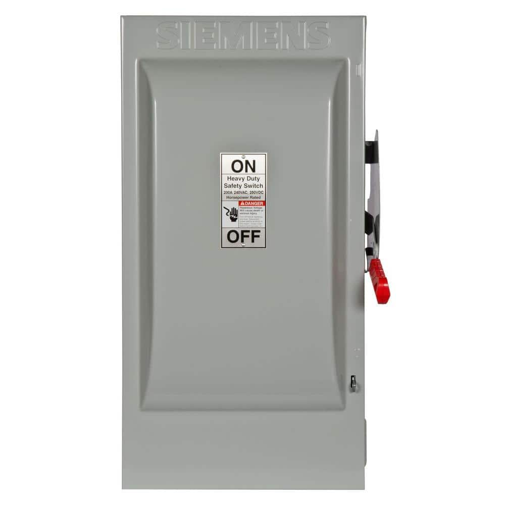
Siemens Heavy Duty 200 Amp 240-Volt 2-Pole Indoor Fusible Safety Switch with Neutral HF224N - The Home Depot
Heavy Duty Safety Switches are available in 30-1200 Amp ratings and in type 1, 3R, 12 and 4X enclosures. Both fusible and non-fusible versions are offered, they can be used on circuits that are rated through 200K when protected by or used with Class R or J fuses, they feature quick make and...
www.homedepot.com
Any reason this won't meet the need for 200A fused disconnect that Sol-ark shows in the install manuals?
Don't you require an exterior disconnect? If so:I spent a couple minutes searching and found this , not cheap, but not out of sight.
Siemens Heavy Duty 200 Amp 240-Volt 2-Pole Indoor Fusible Safety Switch with Neutral HF224N - The Home Depot
Heavy Duty Safety Switches are available in 30-1200 Amp ratings and in type 1, 3R, 12 and 4X enclosures. Both fusible and non-fusible versions are offered, they can be used on circuits that are rated through 200K when protected by or used with Class R or J fuses, they feature quick make and...www.homedepot.com
Any reason this won't meet the need for 200A fused disconnect that Sol-ark shows in the install manuals?
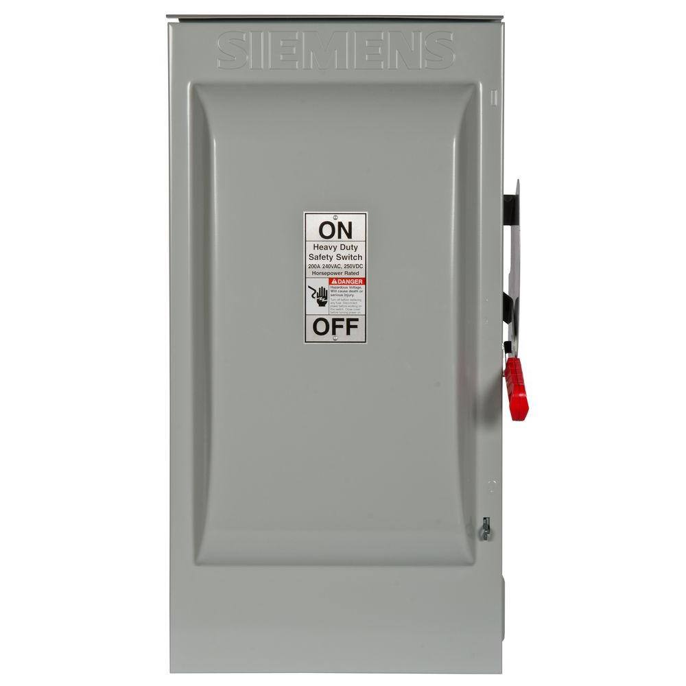
Siemens Heavy Duty 200 Amp 240-Volt 2-Pole Outdoor Fusible Safety Switch HF224NR
Heavy Duty Safety Switches are available in 30-1200 Amp ratings and in type 1, 3R, 12 and 4X enclosures. Both fusible and non-fusible versions are offered, they can be used on circuits that are rated through 200K when protected by or used with Class R or J fuses, they feature quick make and...
www.homedepot.com
Hedges
I See Electromagnetic Fields!
- Joined
- Mar 28, 2020
- Messages
- 20,819
Should be fine, so long as "indoor" meets your needs. Otherwise, want "3R" enclosure. Yeah, "Wet1" found, it, how appropriate!
That one has a neutral bar, which possibly can be grounded. If bonding of neutral occurs elsewhere, add a ground bar.
You may be able to get lugs with stacked terminals rather than using Polaris, to feed SolArk and main panel. May also want 3rd connection for critical loads panel (both it and main panel could bypass SolArk.)
200A in and available to each panel and inverter, but interlocked "generator" breakers probably limited to 125A, so multiple parallel branches to carry more current.
You might want a load-shed relay between SolArk and main panel so if batteries low at least critical loads remain powered. And shutdown of larger loads like A/C before that occurs.
While on this topic, 1) Isn't the disconnect required to be exterior (and close to the meter, or is that optional), and 2) The disconnect doesn't have to be fused, correct? 3) Since N/G bonding typically takes place at the main panel, I'm assuming you mean to just feed the N/G ground on separately and into the SA, but ground the exterior disconnect enclosure? 4) A 3 pole would work as well, correct?
Last edited:
HelloWhile on this topic, 1) Isn't the disconnect required to be exterior (and close to the meter, or is that optional), and 2) The disconnect doesn't have to be fused, correct? 3) Since N/G bonding typically takes place at the main panel, I'm assuming you mean to just feed the N/G ground on separately and into the SA, but ground the exterior disconnect enclosure? 4) A 3 pole would work as well, correct?
Yes there is a stand alone solar only AC input disconnect switch that I am installing outdoors, with instructions on the meter panel that it is around the corner and available to shut down solar to home. My local utility confirmed it can be nearby, as long as there is a permanent sign point to it. The disconnect being discussed here is strictly for the grid feed power coming from the grid through my meter. Sol-ark has diagrams indicating that if you feed your entire 200A service into the Sol-ark , this fused switch is needed. In my case it will be indoors.
See page 8 of this link that shows it.
Maybe I'm missing something here, but wouldn't the 200A fused disconnect located outside coming off the meter serve as the solar AC input disconnect for the SA? I don't see another AC disconnect shown on their wiring diagram.Hello
Yes there is a stand alone solar only AC input disconnect switch that I am installing outdoors, with instructions on the meter panel that it is around the corner and available to shut down solar to home. My local utility confirmed it can be nearby, as long as there is a permanent sign point to it. The disconnect being discussed here is strictly for the grid feed power coming from the grid through my meter. Sol-ark has diagrams indicating that if you feed your entire 200A service into the Sol-ark , this fused switch is needed. In my case it will be indoors.
See page 8 of this link that shows it.
RayofSunshine
New Member
- Joined
- Sep 21, 2021
- Messages
- 98
Just FYI, that manual is at least 2 versions old. The latest one is here.Hello
Yes there is a stand alone solar only AC input disconnect switch that I am installing outdoors, with instructions on the meter panel that it is around the corner and available to shut down solar to home. My local utility confirmed it can be nearby, as long as there is a permanent sign point to it. The disconnect being discussed here is strictly for the grid feed power coming from the grid through my meter. Sol-ark has diagrams indicating that if you feed your entire 200A service into the Sol-ark , this fused switch is needed. In my case it will be indoors.
See page 8 of this link that shows it.
If I understand what you want to do, "Diagram 3" on page 9 of this latest manual (which is not in your version of the manual) is the wiring diagram for your use case.
Ray of Sunshine... wow.. I think you hit the nail on the head here. From looking quickly at diagram 3 it appears that the bypass transfer switch allows movement of the 200A main feed from meter to the sol-ark for normal operation, then if you need to remove the solar-ark you can flip the bypass transfer switch and be back on the grid. Looks pretty close to what I need, I would also need to manually remove the AC coupled solar coming up from my Enphase inverters to the Sol-ark, and install it back into the main panel but that is just a single wire movement no biggie..Just FYI, that manual is at least 2 versions old. The latest one is here.
If I understand what you want to do, "Diagram 3" on page 9 of this latest manual (which is not in your version of the manual) is the wiring diagram for your use case.
Shame on me for just doing a www search for sol-ark 15k manual and not going to the sol-ark www site to ensure I get the latest and greatest.
Just to clarify one more time to wet1.. for my default solar install with Enphase Inverters, code says I must have a stand alone AC solar cut off switch located near the meter. That is not shown in the Sol-ark documents. So at the end of my 200 foot long home run from my panels in the back yard there is a switch installed that just connects or disconnects the solar array from the home.
The additional fused cut off switch is on the line coming from the meter, or the default grid power. All of the other stuff is for Solark.. and I don't fully understand why Solar-ark is insisting that there be a cut off switch on that portion of the circuit.
That is how I understand the diagram.. Cut off 1 is for solar only, Cut off 2 disconnects the main incoming grid entirely to the home. The Bypass switch allows me to go from the main feed connected to the Sol-ark, to the main feed back in place feeding the top of the main panel.
Hope this make sense and I am not getting this wrong
Last question.. Solar manual says that the AC output max is 50A from batteries
Then another 62.5A of AC Power with PV.
Is that second AC power max combined from both AC coupled and DC coupled panels?
Should I assume that in a grid down situation with Solar, and Battery available I can only have 50A+62.5A of power available to run my home?
112.5A? Max for the Solark?
Or are there scenarios where you could start with AC coupled power input, then add battery power as input, then if grid goes down for some extended period and you wanted more power available in home and your AC coupled was maxed out, you could hook up DC solar directly to the Sol-ark 15K.
Can someone help me understand how the input and output power varies as a function of AC coupled, DC coupled and Battery power available, all three or just some combination.
I understand that for AC coupled solar, when batteries are full and grid is down it shuts down the panels until some amount of battery is used up, then turns them back on to re-charge them. It cannot gracefully power them down as it does with DC connected panels.
RayofSunshine
New Member
- Joined
- Sep 21, 2021
- Messages
- 98
Glad I could help.
Please read (my) post #408 in this thread (& attachment) to see if it answers any of your questions re simultaneous AC & DC coupling (direct from Sol-Ark Support).
If it doesn't answer your questions, I'll try to explain it better.
Please read (my) post #408 in this thread (& attachment) to see if it answers any of your questions re simultaneous AC & DC coupling (direct from Sol-Ark Support).
If it doesn't answer your questions, I'll try to explain it better.
Similar threads
- Replies
- 4
- Views
- 232
- Replies
- 14
- Views
- 1K
- Replies
- 17
- Views
- 770