diy solar

diy solar

Solar house generator I started DIY back in 2000 - My path from Trace to Xantrex (on FLA battery) to XW Pro inverters on Tesla Model S batteries

A little change of plans for me.

First I do my taxes and am getting a refund that can help me buy 2 more batteries, and then this happened.

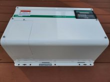
My Trace SW4024 inverter has an internal fan and I was startled with a very loud rattle sound coming from the inverter and determined that the FAN was wobbling and making the noise. I knew the fans fail and this one is 21 years old so after much searching I believe I found a replacement and ordered it for $30. During that search I came across an ebay ad for a Xantrex/Trace SW Plus 5548 inverter for sale. After ordering the fan and revisited the 5548 ad, read what was posted and looked at the beautiful pictures of clean inverter

I then searched and searched and found the operations manual for the unit. I looked up the programming characteristics for this unit and they were similar to my existing inverter's ability. Namely, the support voltages down to 32v while my current unit supports down to 36 volts. And the top charging voltage fits fine, just like my existing unit. So the Tesla charging parameters are fully supported by this 5548 inverter. Sweet!

This inverter supports 5500 watts of load and the better part is, it is a 48volt battery based inverter. I can re-arrange my 6 batteries into 48 volt configuration and swap out my old inverter with the new (to me - it was made in Mar 2005, while my old came from 1999 time frame).

It still is only 120vac for loads, but I can live with that for now.

So I bought it and should get here Feb 17th. Patting myself on the back at the moment, hoping I did right.

here is the seller's remarks:

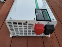
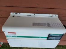
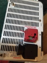
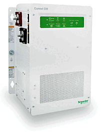
Xantrex/Trace SW Plus 5548 Charger Inverter. Condition is "Used".
This is a Xantrex SW Plus Inverter with 5500 watts and 48 volts of battery in perfect working condition and looks like new.
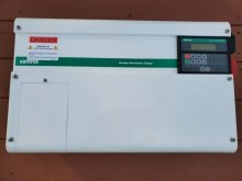
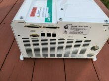
s-l1600-front.jpg

s-l1600-AC side.jpg

s-l1600-bottom.jpg

s-l1600-DC side.jpg

s-l1600-top.jpg
 
Last edited:
One of the biggest reasons to get to 48v battery now, is that my arrays are maxing out their respective controllers. 3 of my arrays are now at 59.9 amps @ 24v, with the 4th at 38amp. I know there are more electrons being lost, that are be restricted due to the 60amp limit of the controllers. SOOOO, I need to get to 48 volts and free up those extra electrons. It is also more efficient for the DC to AC conversion to get to 48 volts instead of the 24v

At the moment, the 4 arrays are putting out a combined 222 amps while my breaker [correction here] between battery and inverter is a 250amp one AND solar charging goes through a 400amp fuse. So that 250a breaker is not in the solar charging path.

If all 4 arrays put out their maximum, I would be at a 239.6 amp max. I prefer to get it back down to a 120 amp flow. That will leave room for more panels over time and some good sized headroom

Yet all in all, some good progress is being made for sure

dougbert
 
Last edited:
One of the biggest reasons to get to 48v battery now, is that my arrays are maxing out their respective controllers. 3 of my arrays are now at 59.9 amps @ 24v, with the 4th at 38amp. I know there are more electrons being lost, that are be restricted due to the 60amp limit of the controllers. SOOOO, I need to get to 48 volts and free up those extra electrons. It is also more efficient for the DC to AC conversion to get to 48 volts instead of the 24v

At the moment, the 4 arrays are putting out a combined 222 amps while my breaker is a 250amp one. If all 4 arrays put out their maximum, I would be at a 239.6 amp max. I prefer to get it back down to a 120 amp flow. That will leave room for more panels over time and some good sized headroom

Yet all in all, some good progress is being made for sure

dougbert

250A thermal-magnetic or magnetic-hydraulic?
We try to limit breakers to continuous current 80% of rating. Midnight says at least some of theirs don't require derating.

Apparently magnetic-hydraulic open only magnetically but have a shock absorber that delays tripping, unless above the fast-trip threshold. I don't know how they are constructed.

Thermal would seem to be better for tracking ampacity vs. temperature of wires, although just matching overall environment/weather and not local conditions of where wires are routed.

Yes, cutting current in half sounds good.

Don't know.

I bought this breaker as a package from Trace back in 2000, using 4/0 cabling.
Temperatures are slightly above ambient, around 68F. Located in the basement

UPDATE/CORRECTION: I updated the original post with this. The 250a breaker is between 4kw inverter and battery. Between the solar charge controllers and the battery is a 400amp fuse, not the breaker, so lots of head room on the panels to battery path.
 
Last edited:
Been watching the tracking on my incoming inverter and got a laugh:

  • Feb 15, 2021
    7:56pm
    Arrived at Facility
    Orem, UT
  • Feb 15, 2021
    7:12pm
    Departed from Facility
    Salt Lake City, UT
  • Feb 13, 2021
    11:07am
    Processing at UPS Facility
    Orem, UT
  • Feb 13, 2021
    11:06am
    Arrived at Facility
    Orem, UT
  • Feb 11, 2021
    11:22am
    Departed from Facility
    Hodgkins, IL
  • Feb 8, 2021
    11:34pm
    Severe weather has delayed the package. It will be delivered as soon as conditions permit.
    Farmingdale, NY


    went to Orem, then Salt Lake City and then back to Orem
It must have forgotten its carry on back at the airport.
 
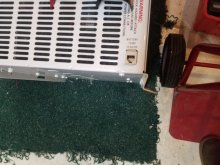
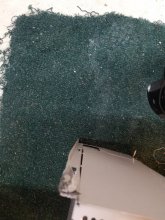
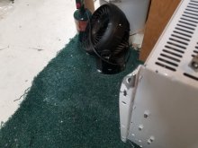
well I got the inverter, but with shipping damage

UPS dropped it off when I was at the dentist and didn't contact my wife.

When I got home I saw damage on one end. The seller doubled packaged it in a plastic tub, surrounded by rigid foam. Nicely packed but after getting the inverter, I noticed 3 damaged areas

1) The plastic POS shroud on the POS connection

20210217_231305.jpg

2) One mounting rail slightly bent

20210217_231301.jpg

3) and the other rail more damaged

20210217_231314.jpg

20210217_231319.jpg

I will call UPS and talk "with them"

But the key will be to see if the inverter will still work. I don't mind the cosmetic issues IF the inverter functions

and yes I failed to take pics of the package and the damage I saw then. It was snowing heavily and I wanted to get it inside and the package was too big for my dolly so I took it apart.

dougbert
 
Last edited:
DROPPED being the key word, did you put enough insurance on it you can get a claim, do it, you may be able to buy a new model.. who knows what damage happened inside, there is NO way I'd accept/keep that.
 
I picked up my network analyzer at the UPS terminal.
Didn't notice until later there was a 3" deep crease across the bottom of the carton. Like someone dropped the 50 pound package on edge of loading dock.
Fortunately shipper put 3" padding on all edges and it came through unscathed.

OP probably didn't sign for his inverter; most shipments are just unceremoniously dumped on the porch. Even if it is a several thousand dollar laptop. So he may be able to claim for concealed damage.

In recent times, my higher value eBay purchases have been "direct signature required", which prevents me from diverting them to the carrier's terminal. Sender has to request that for me.


1613669529431.png
 
DROPPED being the key word, did you put enough insurance on it you can get a claim, do it, you may be able to buy a new model.. who knows what damage happened inside, there is NO way I'd accept/keep that.

it came with free shipping so the sender bought the shipping options so I don't yet know what level of insurance he did. I am waiting on his reply with a direct answer. He has not yet provided a direct answer on this unit

as for getting a newer inverter, the new ones don't have the Tesla charging parameters (lower than lead acid) other than the Sigineer from EVTV
So I will install and see if it works
 
I picked up my network analyzer at the UPS terminal.
Didn't notice until later there was a 3" deep crease across the bottom of the carton. Like someone dropped the 50 pound package on edge of loading dock.
Fortunately shipper put 3" padding on all edges and it came through unscathed.

OP probably didn't sign for his inverter; most shipments are just unceremoniously dumped on the porch. Even if it is a several thousand dollar laptop. So he may be able to claim for concealed damage.

In recent times, my higher value eBay purchases have been "direct signature required", which prevents me from diverting them to the carrier's terminal. Sender has to request that for me.


View attachment 37521

yeah it was just left at the door with NO interaction with the driver.

good to know about the concealed damage option, thanks
 
... and that one does?

yep.

parameters on my current one (SW4024) are
24v DC
Parameterrange VDCmy setting
bulk volts20.0-32.0025.2
float volts20.0-32.025.2
low battery cut out10.0-33.018.5
low battery cut in10.0-35.524.0
high battery cut out10.0-33.025.3
Low Battery transfer to grid10.0-33.019.2


parameters on my new one (55484024) will be
48v DC
Parameterrange VDCmy setting
bulk volts40.0-64.050.2
float volts40.0-64.050.2
low battery cut out32.0-67.839
low battery cut in32.2-67.848.0
high battery cut out32.2-65.050.3
Low Battery transfer to gridNANA


other inverters only allow down to 44 or 42 vdc low battery - on a tesla that becomes UNUSABLE battery storage

on the 5548, that is the difference between 39vdc and 42vdc, that is about 1/4th of the tesla battery range (38 to 50.4)

This new inverter does NOT have the feature of running on batteries until the LOW BATTERY TRANSFER TO GRID, at which point the inverter switches to grid, powering loads AND charging the batteries. When the batteries are at Low batter Cut In, it will then transfer back to batteries
Really nice

My old one has that. The new one does not
it transfers to grid to power the load but does NOT charge the batteries. It relies on solar chargers to re-charge the batteries.
Crazy, eh?
 
Last edited:
My old one has that. The new one does not
it transfers to grid to power the load but does NOT charge the batteries. It relies on solar chargers to re-charge the batteries.
Crazy, eh?

Its All About That Tax Credit.
(only credit on battery would be affected)

 
Its All About That Tax Credit.
(only credit on battery would be affected)


ah, that makes sense - for lawyers and what not, but not for an engineer

The Trace SW4024 I have now was used a lot in India with just batteries to provide businesses with reliable power, since their grid is a sh**storm

I was wondering why they would change that. Now the time difference is between 1999 and 2005 between the two units.

since I am a rebel, I guess I will figure out a way to switch between SB (stand by - UPS) mode and BX mode, manually

I also guess eventually I will get the Sigineer which does the battery cutin/cutout like my current inverter

thanks for the explaination
Great info, i'll have to look at the specs on my SW4048 I already purchased to use on mine (at 48V DC) and see how it compares, I already have thousands invested in Schneider but am loving the updates and community with Victron so may switch, the numbers will determine that, thanks for sharing. Did your EVTV BMS come with the contactors or did you have to purchase them separately?

Jen


are you referring to this one?


Then the manual is


122 pages - read them all, and then forcus on charging and operation on re-reads


for custom charging numbers see page 4-20/table 4-11 - DO NOT USE LITHIUM-ION Battery type for Tesla batteries

for inverter CUTIN and CUTOUT numbers see pages 4-11
see page 4-7 table 4-1 for batt type CUSTOM

Parameterrange VDCsuggested setting
bulk volts50.8-64.050.8 (tesla can support 50.4)
bulk termination voltage (this might work fine)50.0-63.250.0
float volts50.0-64.050.0
absorption40.0-64.050.0
low battery cut out40.0-48.040.0 (tesla can go to 38volts) you lose 2 volts
low battery cut in??probably not available on your inverter, just on my old one
high battery cut out58.0-68.050.4 (NOT POSSIBLE) would have to rely on ESP32 BMS to disconnect in order to protect Tesla batteries
Low Battery transfer to grid??probably not available on your inverter, just on my old one

Using the Low Battery Cut Out and LBCO Delay Settings (page 4-11)

The Low Batt Cut Out setting is the lowest battery voltage level acceptable for use by the inverter. When the batteries discharge to the Low Batt Cut Out setting and are held at or below this level for the LBCO Delay time, the inverter output shuts down and transfers any available AC source (like an AC generator) to the charger to bring the battery level back above the Low Batt Cut Out setting. After shutdown, the inverter does not support any AC loads, and AC loads must be powered by an AC generator.If using an automatic generator starting system, it is recommended to set the Xanbus AGS voltage trigger setting higher than the Conext SW Low Batt Cut Out voltage. Otherwise, inverter output turns off before the generator automatically starts, causing the battery voltage to recover slightly. This may then stop the Xanbus AGS from starting the generator or result in the inverter cycling on and off multiple times before the generator automatically starts.If using an automatic generator starting system with the start trigger set to the same voltage as the LBCO voltage, do not set the LBCO Delay for less than the amount of time it takes the generator to start and connect. Otherwise, inverter output turns off before the generator automatically starts, causing the battery voltage to recover slightly. This may then stop the Xanbus AGS from starting the generator or result in the inverter cycling on and off multiple times before the generator automatically starts

Low Battery Cut Out Hysteresis

Low battery cut out (Low Batt Cut Out) (LBCO) preserves battery life by stopping the inverter when battery voltage drops down to the LBCO value for a few seconds (see LBCO Delay below), then battery charging commences. When charging starts, the voltage level jumps a little but enough that inverting might resume abruptly. Then, battery voltage goes down again and charging starts abruptly. To prevent the inverter from switching abruptly between inverting and charging, the LBCO Hysteresis value is added to the LBCO value to allow the battery voltage to reach a sufficient energy capacity level before inverting resumes. This feature contributes to battery health.See “Advanced Features Menu” on page4–37.

Low Battery Cut Out (LBCO) controls when the inverter stops producing AC output due to a low battery voltage condition. The inverter will stop producing AC output only after this level has been reached for the period of time set by the LBCO Delay. This setting is not temperature compensated.

Hi Batt Cut Out (page 4-10)

sets the maximum battery voltage at which the inverter will operate. If the battery voltage exceeds this limit for more than one minute, the Conext SW displays a fault message and shuts down. The inverter will not support AC loads when in this condition. If a qualified AC source is present, the unit passes AC through to the loads. The inverter automatically restarts when the voltage drops to 3 volts below the Hi Batt Cut Out setting. If battery voltage continues to rise after shutdown, an external charger may still be charging the batteries. The Conext SWcannot control how external chargers operate.

DISABLE/TURN OFF EQUALIZE FUNCTION

Configuration sheet on page 4-39

Jen, send me a private message for more communications like phone number
 
Last edited:
Did your EVTV BMS come with the contactors or did you have to purchase them separately?

Jen

The ESP32 comes with 2 contactors inside the box, 1 for POS and 1 for NEG

if you are referring to the contactors which I control incoming array lines, I bought those separate, around $115 each (4 for 4 arrays) and then wired up the relay to enable/disable then using the ESP32 CHARGE signal to turn on/off the relay
Thank you, i knew you had to get the array ones, was curious about the ESP ones, excellent, thanks..
 
are you referring to this one?


Then the manual is


122 pages - read them all, and then forcus on charging and operation on re-reads


for custom charging numbers see page 4-20/table 4-11 - DO NOT USE LITHIUM-ION Battery type for Tesla batteries

for inverter CUTIN and CUTOUT numbers see pages 4-11
see page 4-7 table 4-1 for batt type CUSTOM

Parameterrange VDCsuggested setting
bulk volts50.8-64.050.8 (tesla can support 50.4)
bulk termination voltage (this might work fine)50.0-63.250.0
float volts50.0-64.050.0
absorption40.0-64.050.0
low battery cut out40.0-48.040.0 (tesla can go to 38volts) you lose 2 volts
low battery cut in??probably not available on your inverter, just on my old one
high battery cut out58.0-68.050.4 (NOT POSSIBLE) would have to rely on ESP32 BMS to disconnect in order to protect Tesla batteries
Low Battery transfer to grid??probably not available on your inverter, just on my old one

Using the Low Battery Cut Out and LBCO Delay Settings (page 4-11)

The Low Batt Cut Out setting is the lowest battery voltage level acceptable for use by the inverter. When the batteries discharge to the Low Batt Cut Out setting and are held at or below this level for the LBCO Delay time, the inverter output shuts down and transfers any available AC source (like an AC generator) to the charger to bring the battery level back above the Low Batt Cut Out setting. After shutdown, the inverter does not support any AC loads, and AC loads must be powered by an AC generator.If using an automatic generator starting system, it is recommended to set the Xanbus AGS voltage trigger setting higher than the Conext SW Low Batt Cut Out voltage. Otherwise, inverter output turns off before the generator automatically starts, causing the battery voltage to recover slightly. This may then stop the Xanbus AGS from starting the generator or result in the inverter cycling on and off multiple times before the generator automatically starts.If using an automatic generator starting system with the start trigger set to the same voltage as the LBCO voltage, do not set the LBCO Delay for less than the amount of time it takes the generator to start and connect. Otherwise, inverter output turns off before the generator automatically starts, causing the battery voltage to recover slightly. This may then stop the Xanbus AGS from starting the generator or result in the inverter cycling on and off multiple times before the generator automatically starts

Low Battery Cut Out Hysteresis

Low battery cut out (Low Batt Cut Out) (LBCO) preserves battery life by stopping the inverter when battery voltage drops down to the LBCO value for a few seconds (see LBCO Delay below), then battery charging commences. When charging starts, the voltage level jumps a little but enough that inverting might resume abruptly. Then, battery voltage goes down again and charging starts abruptly. To prevent the inverter from switching abruptly between inverting and charging, the LBCO Hysteresis value is added to the LBCO value to allow the battery voltage to reach a sufficient energy capacity level before inverting resumes. This feature contributes to battery health.See “Advanced Features Menu” on page4–37.

Low Battery Cut Out (LBCO) controls when the inverter stops producing AC output due to a low battery voltage condition. The inverter will stop producing AC output only after this level has been reached for the period of time set by the LBCO Delay. This setting is not temperature compensated.

Hi Batt Cut Out (page 4-10)

sets the maximum battery voltage at which the inverter will operate. If the battery voltage exceeds this limit for more than one minute, the Conext SW displays a fault message and shuts down. The inverter will not support AC loads when in this condition. If a qualified AC source is present, the unit passes AC through to the loads. The inverter automatically restarts when the voltage drops to 3 volts below the Hi Batt Cut Out setting. If battery voltage continues to rise after shutdown, an external charger may still be charging the batteries. The Conext SWcannot control how external chargers operate.

DISABLE/TURN OFF EQUALIZE FUNCTION

Configuration sheet on page 4-39

Jen, send me a private message for more communications like phone number
Thank you sir... that's great info, I appreciate you taking the time... when people on the Victron forum (Victron owned forum) asked for the low voltage cutoff to be lowered for Tesla packs, they pushed new firmware, with Schneider I couldn't even get a response to a support ticket I filed, time will tell... but thank you, that's the inverter correct... and again thanks for the work you put into your post.
Jen
 
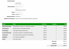
Starting to order my stuff as well.... thanks for posting your build list / receipt, it made it much easier to do mine..

Although, I must say, what I saw on the bottom of the receipt (see below) saddened me ... :(

Jen
1613770286323.png

1613770439238.png
 
Fantastic!

Glad to be of help. I sure like to to share my experiences so others don't re-learn my bad choices


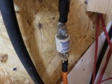
I did order the fuse holder, but ended up NOT using it. If you can cancel that item it will save you $53.

I did inline the fuse between the ESP32 and the main DC buss bar. Black cable on left heads off to the inverter


inline fuse.jpg

I guess you didn't get the memo
They installed an email forwarder on to heaven....................
 
Last edited:
I did order the fuse holder, but ended up NOT using it. If you can cancel that item it will save you $53. I did inline the fuse
Thanks, I plan on mounting the fuse holder on the back wall rather than on the battery terminal itself as Mr. Massey back east mentions in his video how hot it gets and being in Arizona, anything I can do to cut out heat is a win... :) Thank you though.
 
AC for the house is now being run by the GRID only, no solar as I refactor the system and swap out the Inverter


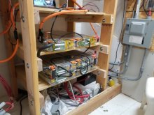
Refactored/Switched the battery from 24V configuration to 48V - to 2S3P
My first batteries are on the bottom row and I add new (to me) ones above the existing ones

20210219_155010.jpg

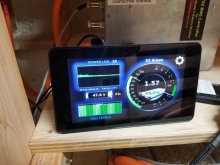
The display showing 47.6 volt AND charging

20210219_155018.jpg

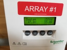
At this moment the 4 arrays had an output of 1576w

20210219_155028.jpg

After the hardware refactor, I needed to modify the software settings:

A) I had to change the ESP34 Pi Display Settings, just one parameter from 6 Series to 3 Series and it took care of the rest

B) Had to modify the charging parameters for the array controllers. Set Array 1 (Device 11), then did a "Copy From Device 11" to each of the other 3. On Device 11,. needed to set 48v battery, the Bulk, Absorb, Float, LBCO, ReCharge levels to 48v entries

The best feeling is that I am NO LONGER max'ing out my charge controllers at 60amps. They should run cooler now

Next Step is the AC side
 
Last edited:
Thanks, I plan on mounting the fuse holder on the back wall rather than on the battery terminal itself as Mr. Massey back east mentions in his video how hot it gets and being in Arizona, anything I can do to cut out heat is a win... :) Thank you though.

talk to me when you do it, as I did it wrong and yes it over heated and I melted the holder a bit
If you look at the above pic, you see how each lug is positioned against the other. I didn't do that the first time
and that is what messed mine up
 

diy solar

diy solar
Back
Top