Nice system. And love the way you did your batteries. Are you still happy with the Growatt?My system is here


You are using an out of date browser. It may not display this or other websites correctly.
You should upgrade or use an alternative browser.
You should upgrade or use an alternative browser.
Use Main Panel as Critical Loads Panel?
- Thread starter lapsmith
- Start date
Hedges
I See Electromagnetic Fields!
- Joined
- Mar 28, 2020
- Messages
- 21,201
No other disconnect unfortunately. How would that help?
Don't know that it would help, but would make it similar to multiple houses each with N-G bond at their disconnect.
It would let you, at the house, remove sources of current you dumped into neutral; those could drive "G" to 120V relative to earth if N was open.
If neutral became disconnected at utility transformer, somebody else could pull N relative to earth and current flows through your ground rod as well. Any significant current and voltage of N rises.
Thanks!Nice system. And love the way you did your batteries. Are you still happy with the Growatt?
Yes I'm very happy with it. I like that it communicates with solar assistant, also, I am able to adjust the settings so when the battery is full it can be throttled from 100% down to 0% without shutting off. That means it works really well with a coupling.
One day someone will figure it out the battery protocol and we will be able to diy batteries for it.
I'll probably be purchasing a second one
zanydroid
Solar Wizard
30VA. They didn’t measure active powerI will have both, a changeover switch and an interlocked panel. Something like this: https://www.amazon.com/dp/B09994XMD...GAT7V4SM&psc=1&ref_=list_c_wl_lv_ov_lig_dp_it
Someone posted that the Growatt ATS-US uses about 30 watts if I'm not mistaken (on battery power no loads).
You’ll need to think about whether you want to switch the neutral when changing over. I’m not sure what’s best.
With the DIN MCBs you can use whatever size breakers you want on each pole and then interlock the handles together. If the breaker has a remote trip I guess a heat detection circuit can go in there too as a backup. On the Growatt the DIN rail only has the ATS contactors and the ganged breakers.
zanydroid
Solar Wizard
Note Hedges pointed out that both the Growatt and Victron actually internally use the same size AT for both 5k and 10k units. They just upsize the components around it to allow higher bypass. It still is limited to the same neutral current on both models.Yes, plenty. I've seen that they do list a 10kva unit, but I've never seen one at any of the typical vendors on line.
I've taken all your comments and created another schematic. As you can see, I am still using the main panel as the critical loads panel, but I think I've addressed all concerns. Do you see any glaring errors? I have some specific questions below.

Questions:
Questions:
- If I use the Growatt autotransformer, it doesn't have an output breaker (verified by Signature Solar). From earlier discussions, it was suggested that I have a disconnect before the autotranformer to avoid parasitic losses (location A on my schematic). If I make that disconnect a breaker, do I also need a breaker on the output side of the autotransformer (location B)? Should that disconnect/breaker also switch neutral?
- If I use the Victron autotransformer, it has an output breaker, but I imagine it is still a good idea to have an input disconnect at location A. I assume the answer to this is the same as for the Growatt.
- For both of the above questions, does it matter whether the output from the inverter (they call it backup) is only on when the grid goes down? If so, the parasitic losses of the transformer would seem to be nil. But some comments mentioned loads through neutral and I'm not sure what that means.
- Should the AC disconnect feeding the inverter switch neutral as well as L1 and L2? I don't know if it matters but the 400 amp disconnect only switches L1 and L2.
zanydroid
Solar Wizard
I assume the wiring from JB to 60A will either be full sized for 400A or feeder tap rule calculations / wiring methods confirmed if you want to reduce the size. And these calculations will need to include the solar backfeed adjustments (could end up being 0 adjustment but calculation should be done to confirm).
Your diagram uses isolation transformer symbol.
Did you ask them to take a picture? I don't trust the support at SS unless you get one of the higher level techs.
Output overcurrent protection
The recommended config is ganged breakers on output with Line breakers at the output rating of the bypass, and neutral breaker I believe set to VA rating of autotransformer (please have someone else check). So 2 pole ganged with 1 pole or 3 single poles ganged together. And these will need to be UL489 primary protection breakers.
The output overcurrent protection may be sufficient to satisfy code of protecting the wiring before the autotransformer. However a breaker might be good to make it easier to service, otherwise you will have to shut down the inverter and confirm that the critical load output is isolated from grid input.
3. If output is on and going through an unloaded autotransformer, the parasitic losses are probably pretty small (just the internal resistance of the transformer). If there is a circuit from AT output to grid through neutral then the loses will go up because the AT will do some balancing work in parallel with grid (assuming output is on). Potentially you can interlock the AT neutral against the grid neutral so they can't touch, however this may not be allowed. And if you do this you will probably need to have an additional N-G bond for the AT side specifically since there will be no path to the N-G bond at the service.
You might be able to gang like 6 breakers together to isolate it all, however you also need to worry about the difference between just tying handles and also tying together trip.
4. Switching neutral. Probably not. Switching neutral is used to avoid double N-G bond, if you don't have that then I think you should avoid switching.
Your diagram uses isolation transformer symbol.
- If I use the Growatt autotransformer, it doesn't have an output breaker (verified by Signature Solar). From earlier discussions, it was suggested that I have a disconnect before the autotranformer to avoid parasitic losses (location A on my schematic). If I make that disconnect a breaker, do I also need a breaker on the output side of the autotransformer (location B)? Should that disconnect/breaker also switch neutral?
Did you ask them to take a picture? I don't trust the support at SS unless you get one of the higher level techs.
Output overcurrent protection
The recommended config is ganged breakers on output with Line breakers at the output rating of the bypass, and neutral breaker I believe set to VA rating of autotransformer (please have someone else check). So 2 pole ganged with 1 pole or 3 single poles ganged together. And these will need to be UL489 primary protection breakers.
The output overcurrent protection may be sufficient to satisfy code of protecting the wiring before the autotransformer. However a breaker might be good to make it easier to service, otherwise you will have to shut down the inverter and confirm that the critical load output is isolated from grid input.
3. If output is on and going through an unloaded autotransformer, the parasitic losses are probably pretty small (just the internal resistance of the transformer). If there is a circuit from AT output to grid through neutral then the loses will go up because the AT will do some balancing work in parallel with grid (assuming output is on). Potentially you can interlock the AT neutral against the grid neutral so they can't touch, however this may not be allowed. And if you do this you will probably need to have an additional N-G bond for the AT side specifically since there will be no path to the N-G bond at the service.
You might be able to gang like 6 breakers together to isolate it all, however you also need to worry about the difference between just tying handles and also tying together trip.
4. Switching neutral. Probably not. Switching neutral is used to avoid double N-G bond, if you don't have that then I think you should avoid switching.
I checked the feeder tap rules and since I am within 10 feet, my conductor size only has to be 10 percent of the supply so 40 amps. Therefore if my understanding is correct, I should be good with 60 amps. The minimum wire size for the feeder taps in my JB is #4 so that's what I'll use. However, in learning about the other rules, it says you cannot have one feeder tap feed another. Bummer. The L1 and L2 feeder taps have an available port, but N doesn't since the 4th port is being taken up by the N-G bond wire. And I assume it is illegal to put two wires into one port. I wonder why one feeder tap can't supply another if they are sized appropriately. Even though though there is a N-G bond at the meter 300 feet away, I don't see how I can remove the N-G bond at the house since they didn't carry the ground wire from the meter the house. So it seems my only options are to get a 5 port feeder tap, or figure out how to connect the inverter's grid connection to a backfed breaker in the main panel. The problem there is that even though the bus bar is the correct size, I have no available space.I assume the wiring from JB to 60A will either be full sized for 400A or feeder tap rule calculations / wiring methods confirmed if you want to reduce the size. And these calculations will need to include the solar backfeed adjustments (could end up being 0 adjustment but calculation should be done to confirm).
Oops, I didn't even pay attention. I will fix it.Your diagram uses isolation transformer symbol.
I was mistaken. It turns out the breaker on the Victron is on the input side. So I'm guessing that means I don't need a breaker on the output side since the input breaker protects the transformer and anything downstream?The output overcurrent protection may be sufficient to satisfy code of protecting the wiring before the autotransformer. However a breaker might be good to make it easier to service, otherwise you will have to shut down the inverter and confirm that the critical load output is isolated from grid input.
TO SAVE TIME, PLEASE SEE EDIT 2 BELOW WHICH MAY MAKE THIS QUESTION MOOT. Just to clarify, the auto transformer will only try to balance if the backup output of the inverter is on when connected to the grid (not in battery backup mode)? Let's say it is on, which I'm not sure why it would be, how does that affect the autotransformer downstream? I don't see how there is a completed circuit since the only possible connection is through Neutral with no return path. This all may be moot since I planned to use a 3 pole manual transfer switch. So unless I forget to switch it to 'off', is that the only way it can try to balance? And if I did forget, is it dangerous or could it damage the transformer? If the answer to that last question is yes, how about adding a relay so that it can't connect unless the grid is off?3. If output is on and going through an unloaded autotransformer, the parasitic losses are probably pretty small (just the internal resistance of the transformer). If there is a circuit from AT output to grid through neutral then the loses will go up because the AT will do some balancing work in parallel with grid (assuming output is on). Potentially you can interlock the AT neutral against the grid neutral so they can't touch, however this may not be allowed. And if you do this you will probably need to have an additional N-G bond for the AT side specifically since there will be no path to the N-G bond at the service.
EDIT: Timselectric did something similar as described in post #1 of this thread: https://diysolarforum.com/threads/growatt-spf-5000-es-at-and-n-g-solutions.36370/
To solve all of these issues, this is what I have done.
1) I ran a neutral conductor from the main panel to the loads panel. (Not bonded at the loads panel)
This provides a neutral for the loads in bypass mode. And provides the N/G bond from the main panel, in all modes.
2) install a relay on the AT feed conductors. Which is controlled by the inverter grounding relay. To only turn on the AT in battery mode.
EDIT 2 Actually, is this even an issue since my main breaker is interlocked with the generator/inverter circuit breaker and therefore the autotransormer can never be connected to the grid.
I saw on one video from U of Maryland (4. Switching neutral. Probably not. Switching neutral is used to avoid double N-G bond, if you don't have that then I think you should avoid switching.
One additional question. The 400 amp disconnect at the meter currently supplies 3 panels. One near the meter (100 amp) one at the house (200 amp) where the taps are, and one at the barn (200 amp) 75 feet away from the house. This totals 500 amps, but is it like the breakers in a panel, where the total of the individual breakers can exceed the main rating, since all loads are not on at the same time?
Last edited:
zanydroid
Solar Wizard
It's only a feeder tap if you reduce the conductor size. So if you add some 400A sized cable it's fine. If it was already reduced to 200A without OCPD then you can't shrink again I thinkI checked the feeder tap rules and since I am within 10 feet, my conductor size only has to be 10 percent of the supply so 40 amps. Therefore if my understanding is correct, I should be good with 60 amps. The minimum wire size for the feeder taps in my JB is #4 so that's what I'll use. However, in learning about the other rules, it says you cannot have one feeder tap feed another. Bummer. The L1 and L2 feeder taps have an available port, but N doesn't since the 4th port is being taken up by the N-G bond wire. And I assume it is illegal to put two wires into one port. I wonder why one feeder tap can't supply another if they are sized appropriately. Even though though there is a N-G bond at the meter 300 feet away, I don't see how I can remove the N-G bond at the house since they didn't carry the ground wire from the meter the house. So it seems my only options are to get a 5 port feeder tap, or figure out how to connect the inverter's grid connection to a backfed breaker in the main panel. The problem there is that even though the bus bar is the correct size, I have no available space.
I think the neutral breaker has to be on the output side. There is no notion of neutral on the input. I don't know about the bypass.I was mistaken. It turns out the breaker on the Victron is on the input side.
I think this is right for an AT but I'm not 100% sure. I haven't thought through in a while how the autotransformer adds or removes current. I believe it definitely does this, so the bypass current on the legs is not guaranteed to be the same as the input current. Some current goes through the coils to do the balancing magic. Also, there is the matter of an internal fault on the autotransformer (and i think this is sufficient to say that you need fusing on both sides because a short in the AT would not be visible to an output side breaker) It's possible that the bypass always sees less than the input because the current is moved to the AT. In which case you might also need input fusing. If the AIO has fusing already internally for that output then this is not necessary to answer.So I'm guessing that means I don't need a breaker on the output side since the input breaker protects the transformer and anything downstream?
(will look at the rest later)
Hedges
I See Electromagnetic Fields!
- Joined
- Mar 28, 2020
- Messages
- 21,201
A breaker on L1/L2 either before or after AT will only protect AT if sized small enough. It would then limit the 240V loads which can be on the same circuit. That is fine if AT is large enough. If you use an AT which is undersized for inverter, consider putting large 240V loads on a separate panel. Or use OCP on AT neutral, or a temperature sensor, in either case rigged to disconnect L1 and L2.
OCP before AT could disconnect if AT faults with shorted windings. But if sized to pass larger 240V loads, probably allows too much current. I think thermal protection plus neutral OCP tripping L1/L2 breakers before AT would give most complete protection.
OCP before AT could disconnect if AT faults with shorted windings. But if sized to pass larger 240V loads, probably allows too much current. I think thermal protection plus neutral OCP tripping L1/L2 breakers before AT would give most complete protection.
ricardocello
Watching and Learning
The Victron 32A autotransformer has a built-in ganged 32A breaker disconnecting L1 and L2 if internal temperature limit is exceeded.Or use OCP on AT neutral, or a temperature sensor, in either case rigged to disconnect L1 and L2.

zanydroid
Solar Wizard
What is the thing on the left, a 24VAC actuated handle thrower?The Victron 32A autotransformer has a built-in ganged 32A breaker disconnecting L1 and L2 if internal temperature limit is exceeded.
View attachment 187205
I had thought it was overcurrent protection for the neutral. Maybe there’s no proper way to set that.
ricardocello
Watching and Learning
I took one apart a year ago, and if I remember correctly there is a thermistor mounted directly on the coil sensing temperature, which goes into the control board, which presumably sends 24v with enough current to trip the left breaker, causing all three breakers to trip when overheating.What is the thing on the left, a 24VAC actuated handle thrower?
I had thought it was overcurrent protection for the neutral. Maybe there’s no proper way to set that.
I did not test it.
Disconnecting neutral is a risky thing, because floating neutrals can destroy equipment.
zanydroid
Solar Wizard
Oh ok, so my guess at how this worked (which I repeated a few times earlier in the thread) was wrong… do I have to go back and manually find and edit all of it, or can I safely assume that people should assume anything they read on the internet is at their own risk….
If someone calls me out on the specific messages I’ll fix it I guess.
If someone calls me out on the specific messages I’ll fix it I guess.
Hedges
I See Electromagnetic Fields!
- Joined
- Mar 28, 2020
- Messages
- 21,201
Yeah, remote trip. A solenoid.
I'm not finding that explicitly stated. Just overcurrent and over temperature.
"Reset", "Shut Release" of the shunt trip
I'm not sure that is actually a "breaker", I'm thinking a solenoid with more turns, suitable for 24V operation. Rather than a breaker which looks like a dead short when voltage applied.
zanydroid
Solar Wizard
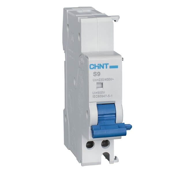
S9 (Shunt Release for NB1, NBH8, NB1L, NBH8LE)| chint global | CHINT
Remote opening of the device when a voltage is applied.1.2 To be mounted on the left side of the MCBs/RCBOs thanks to the special pin.
 chintglobal.com
Here is the data sheet for that component
ricardocello
Watching and Learning
You correctly posted a link to the Victron data sheet. People should read those, and the manuals, and make their own informed decisions!… do I have to go back and manually find and edit all of it,
This forum is a discussion, full of helpful advice from good people. We are not professional engineers with final signature authority.
ricardocello
Watching and Learning
Here is the 100A Victron Autotransformer, different mechanism, same temperature protection.
Note that the coil is identical to the 32A version, same neutral current limitation.

Note that the coil is identical to the 32A version, same neutral current limitation.
zanydroid
Solar Wizard
I took one apart a year ago, and if I remember correctly there is a thermistor mounted directly on the coil sensing temperature, which goes into the control board, which presumably sends 24v with enough current to trip the left breaker, causing all three breakers to trip when overheating.
I did not test it.
Disconnecting neutral is a risky thing, because floating neutrals can destroy equipment.
Do you remember which side of the coil the two pole breaker was on? I wasn’t exactly sure which was the safer/more general purpose side.

Similar threads
- Replies
- 6
- Views
- 462
- Replies
- 5
- Views
- 385
- Replies
- 28
- Views
- 2K
- Replies
- 5
- Views
- 295