diy solar

diy solar

My adventures building a Zinc-Iodine battery

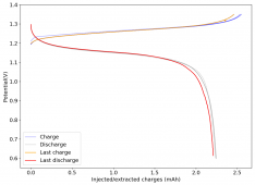
The first WiS (water-in-salt) battery I constructed dried due to some air openings in my Swagelok cell. I added teflon tape to the electrodes to provide a tight seal and prevent contact with the outside environment. I then made a second WiS Zn-I device per the description in the post linked in #24. This is the first cycle:
1633606480545.png
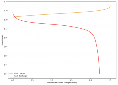
The device was charged to 1.35V and discharged to 0.6V at a current of 5mA (3.87mA/cm2). This first cycle showed a CE of 88% with an EE of 78%. The measured capacity is 2.23mA/h, given the dimensions of the device, this gives an energy density of 62 Wh/L. I will keep cycling it and post some more results.

This is the best device I have ever built! ?
 
Last edited:
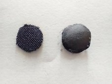
After 4 cycles, the battery had a big voltage drop and seems to have failed. After opening it up, it seems the Whatman filter paper reacted with the Iodine or most of the iodine got deposited in it instead of the carbon cloth. I took a picture for you guys.

IMG_20211007_100145645.jpg

HB-1070 cathode on the left, Whatman 42 filter paper separator to the right. I decided to change back to Fiberglass to see if I could solve this stability issue. This adds 200um to the battery, making the total thickness around 550um. This is because the fiberglass I have is very porous, so I need at least 4 layers (at 100um each), to avoid shorting.

It is also worth noting that I am charging/discharging at around 10x the current level of the paper where I took this idea from, where they cycle the battery at around 300uA/cm2.
 
First cycle of the glass separator WiS battery. I used four layers of fiberglass separator and an HB-1070 cathode. Charged to 1.35V, discharged to 0.5V at 5mA. CE = 87.9%, EE = 80.73%, Thickness = 0.055cm, Diameter = 1.29cm2, Energy Density = 30.43Wh/L, Mean Discharge Potential = 1.27V.

1633624895940.png
 
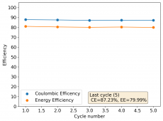
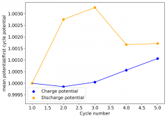
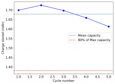
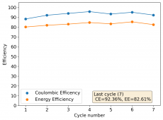
First five cycles of the battery first tested in #31:

1633636640641.png
1633636654249.png
1633636666843.png
So far, there is some loss in initial capacity, which matches the WiS paper results. If my results continue to match, we should see a decrease in capacity for the first ~50 cycles, followed by an increase in capacity for the following 100+ cycles. Last cycle CE and EE values remain very high.
 
Last edited:
The battery from #31 experienced failure after 7 cycles, from what seems to be a dendrite related problem. It might be that this WiS approach leads to dendrites at these higher current levels compared to those in the paper. However, I also realized that my fiberglass was failing because I was tightening the Swagelok cell too much upon closure, which squished the fiberglass into the cathode and caused shorting unless I used 4 layers. This also likely made dendrites much worse as it compacted the electrodes together too much.

I now built a WiS device using a CC6P cathode (350um) with only 2 layers of fiberglass separator (260um each)(total thickness of 870um). Taking care not to tighten beyond just contact of the electrodes. I did not get any shorting at all, despite only using 2 fiberglass layers. This test uses my thickest carbon cloth material and less fiberglass. I am going to cycle at 5mA from 0.5-1.35V and see if I get the same failure mode.
 
Last edited:
Also note I decided to charge the battery described in #33 to 1.3V instead of 1.35V, since upon starting the first charging cycle I noticed that the CC6P cathode has greatly increased the capacity.
 
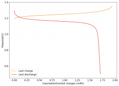
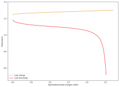
The CC6P cathode really changed the dynamics of the battery. This carbon cloth is significantly thicker, at 350um, and the total cell thickness is now larger at 870um. However, the internal resistance of the battery is also significantly lower and the potential increases much more slowly, so I was able to increase the current to 15mA (11.6mA/cm2) and only charge the battery to 1.3V. There is no exponential runup at the end, which means that I'm probably under-charging the battery. However, I want to test how many cycles I can get before damage under these conditions. The first cycle is shown below:

1633654825746.png
CE = 92.90%, EE=77.96%, MeanV=1.17V, Capacity = 2.51mAh, Energy Density = 26.17Wh/L.

I'll post more graphs as the testing progresses!
 
Last edited:
Plating battery electrodes in the WIS seem to be a good way to produce an cathode filled with I2 instead of using ovens or vacuum chambers,but doesn't show a good result in cycling stability for now.
If the I2 is successfully confined in a nanoporous carbon cloth substrate,you may go back the previous paper A sustainable aqueous Zn-I2 battery which show a great cycling stability.Use the cathode produced in the WIS and then switch the electrolyte and battery structure to the paper one.
After all, solving the stability problem is where it all starts.
That's just my little suggestion.
It is an interesting idea, to make the iodine electrode electrochemically in WiS and then swap it. I'll leave it as a possibility for a future test.
 
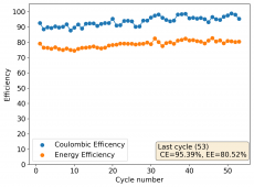
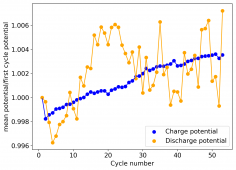
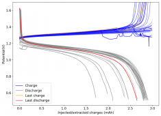
After 53 cycles charging to 1.3V and discharging to 0.5V at 15mA (battery made in #36), the battery capacity has dropped to around 40% of initial capacity. The CE and EE remain very high at 95% and 80% on the last cycle. In accordance with the paper, we have now observed a drop of 50-60% of capacity during the first 50 cycles of the battery, question is if we'll observe the aggressive capacity recovery and surpassing that they saw when running the battery an additional 300 cycles.

1633693458221.png
1633693471963.png
1633693485793.png
In any case, the battery has now avoided death, so it seems battery death was indeed caused by excessive pressure when closing the Swagelok cell.

I will keep cycling the battery to see what we get ?
 
Last edited:
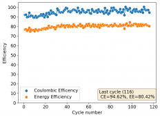
It is interesting to note that as the cycle number has increased the CE has reached higher and higher values, some cycles reaching very close to 100%. This does mean the electrochemical process is becoming more stable as a function of time and it is something not observed in the original WiS paper, where the CE is consistently around 90%.
 
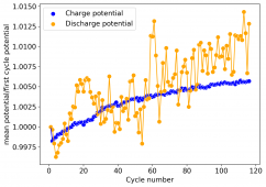
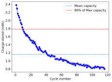
I have now run the battery built in #31 for 116 cycles. The results are below:

1633722546633.png
1633722561005.png
1633722581658.png
Contrary to what the original WiS paper shows, there has been no increase at all in the capacity after the initial 20-50 cycle decline. The discharge capacity at constant voltage charging has been dropping logarithmically from the start up until cycle 116. However, the battery is NOT dead! ?

I am now going to stop this test and try charging to constant capacity (3mAh) and see how the CE and EE do.
 
Last edited:
Charging the battery to 3mAh can be done with a final charging potential below 1.35V (from charging to 0.9mAh to 3.0mAh there was only a 50mV increase in charging potential). Charging these batteries to constant potential might be a mistake - as the charging potential required might increase slightly as a function of cycle number - so charging to constant charging capacity might be a better approach (if the CE and EE can remain high and the battery does not die with cycling).

First cycle of this charging to constant charging capacity is shown below. CE= 98.95%, EE=82.21%, Discharge Capacity = 2.87mAh, Mean Discharge Potential = 1.2310V, Energy Density = 31.48 Wh/L

1633724167152.png
This shows that the battery did not lose its ability to store charge at all, it just had a small increase in internal resistance after 116 charging cycles to constant voltage (1.3V).

I am continuing to cycle it charging to constant charging capacity (at 3mAh) we'll see if it can keep the discharge capacity, CE and EE from dropping and if it doesn't get damaged as a function of time.

Also note, the above graph is perhaps one of the best charge/discharge curves I have ever posted!! ? I can't believe I got a CE close to 100% and an EE > 80% with a >30 Wh/L capacity with a Zn-I battery :eek:
 
Last edited:
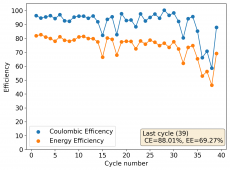
I ran the battery for 46 cycles of charge to constant capacity at 3mAh at 15mA:

1633778233075.png1633778245519.png
1633778259319.png1633778587502.png
Capacity held for around 30 cycles, then there started to be some evident loss of capacity. It seems that the battery cannot be reliably charged/discharged at 15mA, internal resistance starts to increase too much which caused potentials to get abnormally high to reach 3mAh, which probably started damaging the battery.

Before disassembling this battery I have short circuited the battery for 5 min (to ensure complete discharge) I am then going to try cycling to 30mAh at 10mA, see if I see any significant difference.
 
That cycling inevitably damaged the battery built in #31. I therefore built another one from scratch using the same process. Two layers of fiberglass, a CC6P cathode and the WiS solution. I am going to charge it to 1.3V and discharge to 0.5V but this time I am going to do so at 5mA, as the higher current seems to have played an important part in damaging the battery before.
 
This is going to take a while ? Doing the first charging cycle at 5mA to 1.3V, the battery charged all the way to around 9.5mAh. If I am able to discharge to 9mAh (which would be around 95% CE) at an average discharge voltage of 1.1V, this would give a total energy density of 88Wh/L. I will post the first curve in a few hours, when the first cycle is done.

Per the article, it seems the kinetics of the WiS approach are a bit limited, so it will take a lot longer to get cycling results. However, I am intrigued to see how this affects the stability of the battery. I suspect it will take around a week to get the first 50 cycles.
 
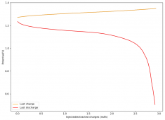
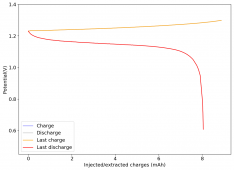
First cycle. charge to 1.3V, discharge to 0.5V, current 5mA, CE=90.45%, EE=80.95%, Energy Density=79.50Wh/L, Discharge Capacity=7.86mAh, Mean Discharge Voltage=1.1352V.

1633810705575.png
 
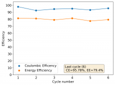
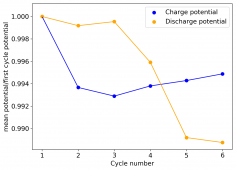
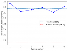
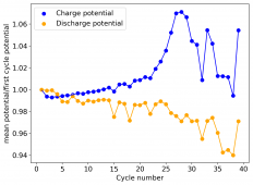
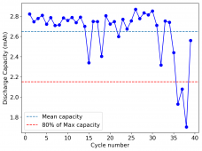
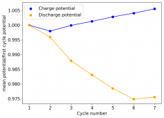
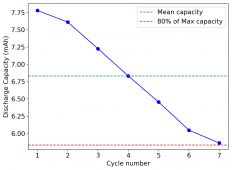
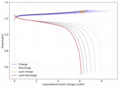
I ran this battery for 7 cycles at 5mA, charging to 1.3V and discharging to 0.5V. I got similar deterioration to what we had seen before, although measured capacities were significantly larger, because of the lower charging current.

1633870695399.png1633870728227.png
1633870741125.png1633870805490.png
Given the constant drop in discharge capacity that is matched with decreases in mean discharge potential and increases in mean charging potential, it seems that the battery gets damaged by increases in internal resistance. This process is not driven by higher current, as the process is happening here, as well as when I charged at 3x this current level.
 
The idea of the WiS (water-in-salt) electrolyte is to diminish the ability of water to dissolve triiodide (I3-) by lowering water activity, forcing water to interact with Zn ions and making ZnIxClxOHx complexes more stable than I3- under this environment. If iodide is forced to coordinate with Zn instead of forming bonds with elemental iodine, then the iodine plating should be stable and the battery much more reversible. This works, given the high Coulombic efficiencies we get, but the lack of stability suggests that there are some processes that are unfavorable that still remain.

I think these processes might be related with water activity. The current electrolyte is a solution that is 15m ZnCl2 and 5m KI. The original paper also tested a 20m ZnCl2 5m KI electrolyte, which had much worse results, as the viscosity of the mixture increases drastically as you add more ZnCl2. However, you can add another chloride salt - which does not allow for coordination chemistry - to reduce the water activity without increasing viscosity too much.

I have now created a 15m ZnCl2, 5m KI, 5m NaCl electrolyte and will be testing it to see if this in fact increases the stability of the battery. This is the highest NaCl concentration I could get, as adding more NaCl (>7m) causes a lot of the Zn salts to precipitate.

Note: Concentrations here and in the paper are given as molal concentrantion (lower case m) which means moles of solute per volume of solvent. This is not to be confused with molar concentrations (capital M) which means moles of solute per volume of solution.
 
Last edited:
diy solar

diy solar
Back
Top