diy solar

diy solar

My adventures building a Zinc-Iodine battery

For the first experiments I have been using Cu anodes (easily cut from copper tape), which have been easy to adhere to the Titanium electrodes and sand to reveal pristine copper. I also sanded down the Ti electrodes (320 and then 240 papers) before these experiments to ensure they are much more flat as they previously had some small irregularities due to the way in which they were cut.

The results so far have been really good, without any dendrites, when using a fiberglass separator. I was even able to run a cell for 141 cycles at 10mA/cm2 with a single layer of fiberglass separator with no issues (Exp 3b).

However, I am still experiencing substantial capacity decay. The fact that the decay is slower at higher current (10 mA/cm2 Vs 5 mA/cm2) (Exp 3a and 3b), suggest that the decay is related to some species that are generated and diffuse away from the electrodes. Since there is less time for diffusion at higher current, you expect diffusion related decay to be less prominent as electrode cycling becomes faster. This also matches the fact that Coulombic efficiency increased with current (97 at 10 mA/cm2 Vs 93 at 5mA/cm2).

I am now running an experiment (Exp 4) including 1M NaCl in the solution, to see the effect of further reduced water activity. After this is done I will run additional experiments at 2M NaCl and 5M NaCl, to see the effect this additive has on cycling characteristics.
 
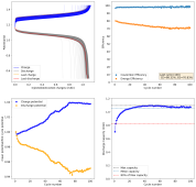
Exp12 is giving some really interesting results. It uses a copper anode, a Spectracarb 2050A-0850 Cathode, 3 layers of fiberglass separator and an electrolyte made of 15m ZnCl2 + 5m KI + 1m NaCl in distilled water. I am testing this at a current density of 10mA/cm2, charging to 1.45V and discharging to 0.5V.

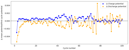
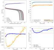
So far the battery has cycled exactly 100 times. This is the first time potential and capacity changes have seemingly stabilized. Coulombic efficiency is also now consistently in the >97% region. No dendrites have appeared yet either.

1637686962570.png
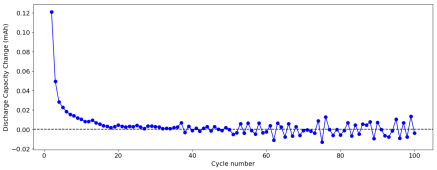
The graphs below show the changes in capacity and changes in potential as functions of cycle number:

1637687013676.png
1637687127138.png

Capacity is at around 1.07mAh, given the volume of the battery of 0.1032cm^3 and an average discharge potential of 1.03V, the energy density of this battery is at 10.88 Wh/L. The most exciting aspect of this battery is its stability so far, which I hadn't been able to achieve before. I'm going to run it until it decays to 20% of max capacity, dies due to dendrites or reaches 2000 cycles?.
 
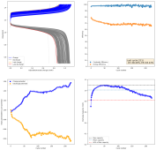
The battery ran for 222 cycles. Decay became significantly more pronounced during the last 30 and the stability in the potentials was only temporary, there were also some small dendrite issues. So far this is the battery I have cycled for the longest yet.

1637753152280.png
 
Hello Daniel,

I have an interesting design and application for a titanium dioxide-based battery. Do you make and test batteries as a hobby or is it your business?
 
Hello Daniel,

I have an interesting design and application for a titanium dioxide-based battery. Do you make and test batteries as a hobby or is it your business?

I do it as a hobby, I have no plans or goals to ever make any of this commercial. It is just to learn and share with anyone interested.
 
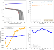
This is Exp21, using CCP cathode, 3 layers of fiberglass separator, copper anode and the regular ZnCl2 15m + KI 5m electrolyte. This cell is being cycled between 0.8V and 1.275V at 10mA/cm2. So far 100 cycles and the battery capacity went down and then back up close to max capacity.

1638131294301.png

I decided to cycle only to 0.8V because the copper anode seemed to face some deterioration when cycling down to 0.5V. The current capacity of this battery is on the lower side - energy density is around 4Wh/L - I want to see for how long it lasts under these conditions. Mean charge potential seems to be stable for now. Coulombic efficiency is in the 96-97% range, energy efficiency is in the 82-83% range.

Will this battery finally be long term stable?
 
I am now repeating Exp12 - the longest lasting yet at 222 cycles - but using a Zn anode instead of a Cu anode to see what effect this has. All other variables are exactly the same.

So these results were still very similar, an increase of capacity up until a maximum, then a linear decline of capacity that doesn't stop. Even with CE values above 98% this decay doesn't cease to exit. Something forms that causes these Zn-I batteries to decay and die with time, sadly I don't have the tools to figure out exactly what it is.

Given that it happens with a variety of anodes and cathodes, it is likely related with some impurity in the solution or with some aspect of the chemistry at high current densities that wasn't addressed on the paper I used as a basis for these batteries.

Because of this road block I might need to change the chemistry I study, yet again.

So far I have yet to see a chemistry that is stable enough, both Zn-I and Zn-Br suffer from very big problems in terms of side-reactions that damage the electrodes or the electrolyte and cause big capacity or efficiency losses as a function of time.

I might try someone's previous suggestion to study the Zn-MnO4 chemistry, which is pretty benign to work with at home.
 
I invite you to follow my new thread on Zn-MnO4 batteries


This doesn't mean I won't continue doing Zn-I experiments at some point.
 
I invite you to follow my new thread on Zn-MnO4 batteries


This doesn't mean I won't continue doing Zn-I experiments at some point.
Thanks for sharing, and good luck with the new experiment, also Sodium ion battery looks like a worthy candidate....
 
Thanks for sharing, and good luck with the new experiment, also Sodium ion battery looks like a worthy candidate....

Sadly Sodium ion batteries require inert conditions for assembly (no water or oxygen) so I cannot do that at home.
 
I invite you to follow my new thread on Zn-MnO4 batteries


This doesn't mean I won't continue doing Zn-I experiments at some point.
I am relatively new to the forum and just found this thread. It is fascinating. I will look up your blog later.

In the meantime, I have a few questions:
1. How do you decide what charge density to apply for different tests? Sometimes you use 2.5mA/cm2, sometimes 5.0mA/cm2, etc.
2. Would it help to use a teflon o-ring to help seal each electrode rather than the tape?
3. Rather than using copper foil tape for an electrode tip, what about plating the electrodes? It seems that nickel, copper, silver, and gold might be potential candidates, and my understanding is that you can plate them directly onto your carbon rod electrodes.
4. Is it possible with your setup to explore different pressures on the electrolyte? I'm actually more curious about what might happen with the cell in a relative vacuum, but higher pressure might also be a possibility.
5. Is discharge depth causing the dendrite formation? What happens if you cycle the cell and avoid the deep discharge knee?

Thanks for sharing your work!

Many regards,

- Just Gary

Thanks for reading the thread. Here are my answers:
  1. Depends on what I want to test. Tests with lower current take longer, but are much more susceptible to Coulombic losses caused by diffusion, however, they lead to less side reactions (as potentials are lower). By comparing high and low current tests you can learn a lot about what is causing losses in your devices and potentially how to improve them.
  2. It wouldn't be better in terms of performance, but perhaps more practical. I don't have one though.
  3. Plating has a lot of variables and takes a lot of time. Different plating conditions can generate different crystalline phases and different results. On the other hand placing a copper tape electrode takes me less than a minute and is really reproducible. It is hard to make plating a reproducible process, it has a lot of parameters (temperature, concentration, potential, current, additives, reagent purity, etc). But sure, you could plate electrodes. A condition is that the metal has to be able to be wet by zinc, so forget about using nickel, as zinc will not plate well on it.
  4. Electrolytes are incompressible and have low vapor pressures, so testing vacuum or high pressure on electrolyte is not going to change the electrochemistry.
  5. Not really, even shallow discharges will lead to dendrite formation with time. Deep discharges actually help, by dissolving more Zn. However the problem is really not solvable by manipulating cycle depth. Current density plays a much bigger role.
 
Last edited:
During the first winter of Covid I found the channel then watched all the Nile Red Videos.


Learned more then back in school.
 
With all my recent work in flow batteries in the Zn-I system, I decided to take a new look into Zn-I batteries. In particular a few new papers on back-plating of Zn exist, which is an interesting geometry solution to the problem of dendrite formation. I had never tried it before because I lacked a practical way to achieve it, but now I think I have a potential solution.

See this nature paper (https://www.nature.com/articles/ncomms11801) for more on the backplating configuration. It seems if we can do backplating of Zn in a Water-in-salt-electrolyte (WISE) configuration (https://onlinelibrary.wiley.com/doi/full/10.1002/ange.201909324), we could have a battery that could be rid of the dendrite issue while still providing the benefits of solid formation in the anode, avoiding all I3- formation.

I used the WISE electrolyte on my post successful trials in this thread but I could never get rid of the Zn dendrite problems.
 
Wow you've done a lot since I've last read your ZnBr thread.
With regards to dendrites two ideas come to mind, Redflow does %100 depth of discharge cycles to help prevent dendrites.
Another is a more rigid barrier. perhaps a neutral plate between the cathode/anode would force the dendrites to grow around the obstacle, similar to the backplate idea. or a porous ceramic material (that's obtainable) I haven't found anything yet.
I wonder if just stopping every 50 cycles and fully discharging the cell to 0v could help effectively prevent long-term dendrite growth (its a lot simpler then additives).

https://www.sciencedirect.com/science/article/pii/S2666386422000947 - i have zero idea if this would survive the WIS electrolyte environment.

I do love this back-plating idea. super curious.
Best of luck, i cant wait to see your results and thanks for taking the time to share your results with the community.
 
Last edited:
Wow you've done a lot since I've last read your ZnBr thread.
With regards to dendrites two ideas come to mind, Redflow does %100 depth of discharge cycles to help prevent dendrites.
Another is a more rigid barrier. perhaps a neutral plate between the cathode/anode would force the dendrites to grow around the obstacle, similar to the backplate idea. or a porous ceramic material (that's obtainable) I haven't found anything yet.
I wonder if just stopping every 50 cycles and fully discharging the cell to 0v could help effectively prevent long-term dendrite growth (its a lot simpler then additives).

https://www.sciencedirect.com/science/article/pii/S2666386422000947 - i have zero idea if this would survive the WIS electrolyte environment.

I do love this back-plating idea. super curious.
Best of luck, i cant wait to see your results and thanks for taking the time to share your results with the community.

Thanks for posting!

Doing deep discharge cycles works to some extent but it doesn't really solve the problem fully.
 
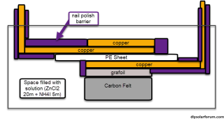
I have done some first tests using the following architecture:

1696877833176.png
Basically strips of copper tape are first placed on a square of PE sheet, then a copper tape disc (sanded to a clean surface) and grafoil strip are placed on the anode and cathode sides respectively. A carbon felt is then glued to the grafoil's corners to secure it in place, the copper tape disc adheres using its adhesive. All exposed conductor surfaces are then insulated using nail polish to prevent any electrochemical behavior except for on the carbon felt and the copper disc anode. I used a 20m ZnCl2 + 5m NH4I solution (I ran out of potassium iodide, so I used ammonium iodide for the test). This is a Water-in-salt electrolyte (WISE). The setup is fully immersed in around 2mL of the solution.

As you can see, the above geometry ensures the Anode doesn't face the cathode and there are no direct paths for dendrites to cause a short. They would need to grow all around the electrolyte to achieve that.

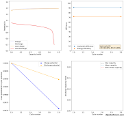
I did a couple of cycles at a current density of around 2mA/cm2, charging to 0.5mAh and discharging to 0.7V. The results are promising:

1696878616978.png

The Coulomb efficiency is quite high, above 90%, so we definitely do not get any major soluble triiodide formation in the electrolyte. All the iodide seems to plate as elemental iodide in the carbon felt (in agreement with published WISE results using KI+ZnCl2).

The loss in energy efficiency from the distance between the electrodes also seems to be limited, thanks to the high conductivity of the WISE electrolyte, even though the distance from anode to cathode is quite large as you need to go all around the PE sheet. Plating on the copper electrode looks very regular, at least from a first glance. There aren't any discernable dendrites at this state of charge (SOC). Note that higher EE value are likely achievable when charging at lower current density.

Note that the theoretical energy density you could get from this electrolyte is around 134 Ah/L (around 160 Wh/L at 1.2V) . For reference lithium iron phosphate is normally at around 220 Wh/L. The volume of the cathode material used is 0.26mL, so I would expect the cathode to hold 35mAh at a max.

A battery with this type of backplated configuration cannot be easily rolled, so likely instead of going for very fine separators and high voltage efficiencies a battery like this would work more like a lead acid battery, with larger cells stacked in rows. Basically arrays like the one I showed above stacked together to fill a box with the electrolyte then poured over to fill all the space and fill all the felt (which might require some vacuum to fully achieve wetting of the entire all the surface area.

I am now cycling this battery to 25mAh, which will take a long time per cycle, but I just want to see if it reaches the capacity and how dendrites behave at high SOC.
 

diy solar

diy solar
Back
Top