Well darn, thanks for replying.Unfortunately I can't recommend it because it died after 12 hours of use.
You are using an out of date browser. It may not display this or other websites correctly.
You should upgrade or use an alternative browser.
You should upgrade or use an alternative browser.
Cinergi's 28 kWh / 4 kW Solar / 10 kW inverter RV build
- Thread starter cinergi
- Start date
Here's my next prototype. Square bar on both sides, 5/16" rod, and I moved the upper and lower sets closer to the center. I'm also using deconstructed CALB flexible bus bars (2 pieces for each series connection). The battery is at about 0% and I set all springs to 30mm and I'll observe changes along the way. I also measured the terminals between the bus bars so I can compare afterwards. Charging at 10 amps - so this will take ~28 hours.
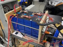

The downside is, this increases the overall length by 2 inches. I'll have two rows of 4 so that's another 8 inches per row. I think I have the space for that but I'll need New Horizons to do some measurements for me. It again makes me think about using 8 cells per fixture...
Cutting the 1x1 square tube with my 6" chop saw and a metal blade wasn't bad but the ends needed a lot of work to clean them up (with a dremel).
I also haven't yet figured out how I'll safely mount these in the RV ... I can't inhibit the movement. Maybe strapping them down lengthwise would work. I'm open to suggestions that doesn't increase the height.
Hedges
I See Electromagnetic Fields!
- Joined
- Mar 28, 2020
- Messages
- 20,660
The downside is, this increases the overall length by 2 inches. I'll have two rows of 4 so that's another 8 inches per row. I think I have the space for that but I'll need New Horizons to do some measurements for me. It again makes me think about using 8 cells per fixture...
Cutting the 1x1 square tube with my 6" chop saw and a metal blade wasn't bad but the ends needed a lot of work to clean them up (with a dremel).
I also haven't yet figured out how I'll safely mount these in the RV ... I can't inhibit the movement. Maybe strapping them down lengthwise would work. I'm open to suggestions that doesn't increase the height.
If you used U-channel instead of square tube, or if you used a hole saw to countersink the spring assembly, you could get back a couple inches.
May need to do something to access stacked nuts if you use those like another member, but that isn't shown in this picture.
Hedges
I See Electromagnetic Fields!
- Joined
- Mar 28, 2020
- Messages
- 20,660
Here's my next prototype. Square bar on both sides, 5/16" rod, and I moved the upper and lower sets closer to the center. I'm also using deconstructed CALB flexible bus bars (2 pieces for each series connection). The battery is at about 0% and I set all springs to 30mm and I'll observe changes along the way. I also measured the terminals between the bus bars so I can compare afterwards. Charging at 10 amps - so this will take ~28 hours.
View attachment 34489
Your battery cable to shunt is an example of what I think could apply torque to the nut and loosen it.
I suggest securing cable in some way. Shunt mounted to the assembly would be one.
Your battery cable to shunt is an example of what I think could apply torque to the nut and loosen it.
I suggest securing cable in some way. Shunt mounted to the assembly would be one.
Thank you -- yes, I know. It's actually not as torqued as you think (and the shunt is held in place with a zip tie). This is only going to be configured as such for 2 days.
If you used U-channel instead of square tube, or if you used a hole saw to countersink the spring assembly, you could get back a couple inches.
May need to do something to access stacked nuts if you use those like another member, but that isn't shown in this picture.
Yeah if I don't have enough room, I'll consider that. I was originally considering unistrut/superstrut.
This was to be expected. Maybe the engineer thought you could get an extra 5 or so amps by taking down to 2 volts...4th test complete. Same as before - 269.
Last edited:
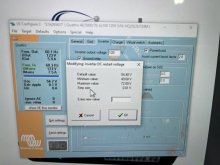
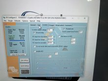
Mine says im on the newest firmware, with no updates available....it is a right bugger not being able to decrease this value down to 1V, which might prove reasonable for the flat curve of lifepo4
When you said yours got fixed, i take it you can lower that value now....what options do you get?
Looks like the min difference is now 1v
Solarfun4jim
Solar seduced :-)
Hmmm, thats a significant percentage difference on that 4th spring. I suppose you will eventually glean more info on repeatability, but i'm certainly curious why that one was different!20% SoC and 3 springs have compressed 0.5mm and 1 by 0.8mm
No terminal movement.
Solarfun4jim
Solar seduced :-)
Many thanks for those screenshots....so it looks like yours is different to mine, since my min default is 2v on a 24v system.
It seems back to front....you have a min of 1v on a 48v sys, i'm 2v on a 24v sys....so you have 4x more accuracy in setting!!!
Hmmm... i wonder if its because i'm on a user mode and not strictly the default Lifepo4 setting? Need to investigate further.
Since the energy is in 3.1v-3.4v, then that 2v minimum on my system becomes more significant to work around. ie if i want to run from 24.8v-27.2v conservatively staying out of the knees, then the minimum restart value would be 26.8v(3.35/cell) Even with the bounce back after the load gets terminated(0.5V), 3.35v/cell is many hours of solar energy to go into the cells before you restart discharge. Consider yourself fortunate you have better parameters to work with.
Edited my original post a little as i made a mistake in my thinking.
Last edited:
54% SoC. I now have 0.4, 0.5, 0.6, and 0.8mm of spring movement. No terminal movement.
@Solarfun4jim my springs have always had pretty significant differences ... I do have some small variations in lining up the cells (they're not perfectly even) and who knows what other contributing factors. I suspect this is pretty normal.
@Solarfun4jim my springs have always had pretty significant differences ... I do have some small variations in lining up the cells (they're not perfectly even) and who knows what other contributing factors. I suspect this is pretty normal.
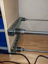
That looks very much like my compression fixture. I was top balancing all 8 cells together this weekend so I made it long enough for 8. My final system will compress four cells per stack (like yours) so I will end up with two compression fixtures.Here's my next prototype. Square bar on both sides, 5/16" rod, and I moved the upper and lower sets closer to the center. I'm also using deconstructed CALB flexible bus bars (2 pieces for each series connection). The battery is at about 0% and I set all springs to 30mm and I'll observe changes along the way. I also measured the terminals between the bus bars so I can compare afterwards. Charging at 10 amps - so this will take ~28 hours.
View attachment 34489
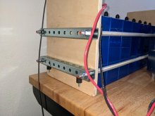
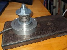
Main difference is I am using Belleville Disc Springs instead of coil springs. Makes it easy to dial in the precise spring constant and travel I need.
This is my spring test fixture. 2000 N (449 lb) capacity load cell.
I plan on using bulkhead connectors mounted into the wooden end plates, then use braided straps to make the connection to the cells. That way pulling on the cable, doesn't pull on the cell.Your battery cable to shunt is an example of what I think could apply torque to the nut and loosen it.
I suggest securing cable in some way. Shunt mounted to the assembly would be one.
I am mounting rubber isolators under the bottom bar. These isolators will thread into cleats secured to the floor of the van. You can see the rubber isolators in the first pic I posted two threads above this one.The downside is, this increases the overall length by 2 inches. I'll have two rows of 4 so that's another 8 inches per row. I think I have the space for that but I'll need New Horizons to do some measurements for me. It again makes me think about using 8 cells per fixture...
Cutting the 1x1 square tube with my 6" chop saw and a metal blade wasn't bad but the ends needed a lot of work to clean them up (with a dremel).
I also haven't yet figured out how I'll safely mount these in the RV ... I can't inhibit the movement. Maybe strapping them down lengthwise would work. I'm open to suggestions that doesn't increase the height.
That way the battery pack is floating, yet secured to the van. This will mean my compression fixtures will need bottoms (to ensure the cells don't slip down over time.
54% SoC. I now have 0.4, 0.5, 0.6, and 0.8mm of spring movement. No terminal movement.
70% SoC. 0.4, 0.7, 0.6, 0.9mm spring movement. No terminal movement.
When you say ‘no terminal movement’ does that mean the bottom is expanding by an average of 0.65mm but the top (where the terminals are) is not?70% SoC. 0.4, 0.7, 0.6, 0.9mm spring movement. No terminal movement.
Similar threads
- Replies
- 2
- Views
- 135
- Replies
- 83
- Views
- 4K
- Replies
- 8
- Views
- 416


