diy solar

diy solar

Enphase Backup Storage - DIY Self-Installer Hurdles

since AC coupling is still new
As @Hedges posted, AC coupling from SMA has been around since 2000 and I think Tesla has been installing Powerwalls since 2016 so I would not call it new in this fast moving technology age. Other than those mentioned above it may still be in the early adopter stage for some people.
 
As @Hedges posted, AC coupling from SMA has been around since 2000 and I think Tesla has been installing Powerwalls since 2016 so I would not call it new in this fast moving technology age. Other than those mentioned above it may still be in the early adopter stage for some people.
OK, I guess then my questions and statements here are in the context of how to successfully apply AC coupling with the new entrants offering the feature (EG Deye and the other hybrid/AIO out of China)
 
OK, I guess then my questions and statements here are in the context of how to successfully apply AC coupling with the new entrants offering the feature (EG Deye and the other hybrid/AIO out of China)
Yes those vendors are new to the game. Very few of them are UL listed so I don't see them having a big impact on the market until they get listed and improve their algorithm. What I don't know is from a global perspective whether AC coupling is a common phenomena because of the different standards around the world. I assume AC coupling is a new concept for you? Have you done a system with AC coupling yet?
 
What I don't know is from a global perspective whether AC coupling is a common phenomena because of the different standards around the world. I assume AC coupling is a new concept for you? Have you done a system with AC coupling yet?

I'm installing another 8kW-AC of Hoymiles microinverters this year and want to AC couple those to the new system in the future. To get a little more endurance and convenience when grid-down in case we keep getting these storm-related power outages in California. AC coupling would be a nice-to-have backup to generator charging.

In terms of global products, SMA is headquartered in Europe and PowerWalls are sold overseas, and Victron supports AC coupling -- they have some tighter/more tested combination to AC couple with a handful of other company's inverters. I've been looking at Victron's AC coupling (they have a new 1741 listed inverter), and some of the unlisted or dubiously listed Chinese inverters that added AC coupling (EG LVX6048WP)
 
Just finished my 1st round of testing AC coupling of a single IQ8+ with Schneider XW Pro 6848, see testing with XW + inverter, no difference.
Testing XW + Inverter and AC coupling

- IQ gateway is not required - i.e. powered off - for the IQ8+ to lock on to the grid or micro-off-grid to produce power
- IQ8+ can lock on to grid-only or off-grid only
- disconnects on a grid fault, but reconnects after a minute and ramps up power to its max within 2 minutes
- stays on when grid comes back online.

Will start large scale testing in about 4 weeks.

Looks like the problems are related to larger scale PV input that approaches the inverter rating. The PV current needs a sink to go.

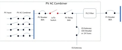
PV Relay: The AC coupling recommendations from Schneider do recommend a PV disconnect relay because power curtailment may be too slow.
I overlooked it several times! Not sure about latest NEC code, but EPO imho requires disconnect relays for PV input and for ESS input, such that the micro-grid is completely de-energized, 48V backup battery is ok, but any AC battery needs to be fully disconnected.
 
Last edited:
quick question about relay to disconnect: is it best to use solid state to avoid arcing ? or would a simple RC snubber sufficient for mechanical contacts ? thanks
 
Relays should be pretty reliable disconnecting AC, but will have a cycle life. An RC snubber would generally be problematic for AC contacts; might work for some loads but with inverter loads could even look like grid power present when not inverting.

Depends on how often cycled.

With a bank of microinverters, I think they could be enabled/disabled in steps. This could be a bank of relays or transistors, which one being selected according to frequency shift (for older microinverters not implementing frequency-watts.) For wear leveling, rotate assignment of microinverters disabled to limit power.

Power is relatively low, 150W to 500W at 240V so 2A max. Could be good to do solid state.
How do the relays perform with 4-quadrant power? (If they work with inductive loads, should handle this.)
 
quick question about relay to disconnect: is it best to use solid state to avoid arcing ? or would a simple RC snubber sufficient for mechanical contacts ? thanks
Typically the circuit being disconnected in an AC coupling situation is AC so no risk of arcs. I don't trust SSRs to disconnect reliably.
 
Actually, there is arcing! You need precise relay timing to hit the AC zero-crossing. Occurred with stacked Schneider XW inverters in the past, that's why they developed and recommend the BSC 2200 MID panel with a 200A MID relay for stacking inverters. We would need PV control logic with AC input to time the disconnect. RC snubbing plus MOV would help extending relay life.

SSR's are reliable but can malfunction, but so can relays with contacts stuck in the closed or open position. SSR's have losses and may need active cooling at high PV feedback amperage.

Best solution would be a dedicated 15-20A SSR for each PV AC substring plus a PV disconnect relay for the combined output. All switching devices protected with MOV's and PV disconnect relay protected with additional RC snubber. Then you'll have a fault-tolerance of 1 and fault-tolerant EPO disconnect! And you could switch on/off substrings per load and SOC. If I did not have a main job I would design and prototype a controller and have it manufactured via Crowd Supply. However, certification would be costly!
 
Last edited:
SSR's are generally not recommended as they typically fail shorted. Normally open contactors don't fail shorted nearly as much.
 
You're correct, but wouldn't the breaker open first or would the SSR fail first if sized correctly? How about zero-cross SSR's?

SSR Protection

We do not need the switching speed of a UPS for the PV backup, so simple relays would work.
For daily operations in an off-grid scenario, individual PV substring relays would be activated/deactivated several times during the day depending on PV production, load diversion controls and backup loads and SOC.

Best solution long-term would be direct power control of the PV inverter via open-standards SB supplements! Then you would need the PV disconnect relay (or contactor) only for EPO and/or 95% SOC in case the power controls fail to communicate with the inverters.
 
Last edited:
Update on AC coupling IQ8's
All single IQ8+ inverter testing was done without any PLC communications between the IQ8 and the IQ gateway, it was switched off.
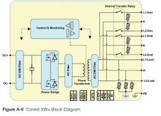
Here is a block diagram for the XW+ or XW Pro inverter:
XW + Block Diagram.jpg
Look at the AC EMI filter on the backup load side where the micro-inverters would be AC coupled to!

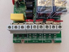
XW Inverter AC Relay Board.jpg
Now check this out, bottom left, 3 AC Load 4.7nf 250V capacitors, from L1, N and L2 to GND!
This will attenuate or kill weak PLC carrier communications!

What could be done?

1) de-solder the capacitors, but there is more EMC filtering downstream, have not fully reverse-engineered the full drawing for the AC relay board. May void warranty, invalidate ETL/UL listing and/or FCC EMI noise filtering rules.
2) Redesign the AC relay board and change the symmetric EMI filtering to asymmetric PLC style filtering.
3) use a directional PLC line filter

Enphase PLC Filter.jpg
If you have access to other inverters, please check the EMI filter on the line where AC coupling with Enphase is done.
Maybe the AC batteries that can be successfully AC coupled with Enphase have directional PLC style EMI filters!
 
Last edited:
I didn't read through this whole thread but
1) doesn't the envoy controller go on the same side as the micros so there would be no PLC issue
2) AC coupling and operation of the micros do not depend on PLC
 
goldserve: #192 is about AC coupling of IQ8's with Schneider XW 6848 inverters or non-Enphase MID controllers/inverters in general, and the use of an additional PV disconnect relay.

1) EMI or other PLC device Interference with Enphase PLC have long been known and have been successfully prevented with a PLC filter.
Enphase has Tech Briefs how to fix PLC interference with a PLC filter. Without a PLC filter, Enphase PLC will RF pollute the house grid and vice versa.

2) Correct! AC coupling does not depend on PLC, as the single IQ7 and IQA tests have shown.
But you need reliable PLC communications to upload data to the Enphase cloud and for TOU and export control.

Quite a few Enphase users shy away from installing the over-priced Enphase PLC filters. Enphase sources these filters from Astrodyne TDI (Radius Power) and applies a 1:5 markup! You can get single-stage Astrodyne PLC filters (split-phase) for less then $100.
 
Last edited:
Update on AC coupling IQ8's
All single IQ8+ inverter testing was done without any PLC communications between the IQ8 and the IQ gateway, it was switched off.
Here is a block diagram for the XW+ or XW Pro inverter:
View attachment 141896
Look at the AC EMI filter on the backup load side where the micro-inverters would be AC coupled to!

View attachment 141897
Now check this out, bottom left, 3 AC Load 4.7nf 250V capacitors, from L1, N and L2 to GND!
This will attenuate or kill weak PLC carrier communications!

What could be done?

1) de-solder the capacitors, but there is more EMC filtering downstream, have not fully reverse-engineered the full drawing for the AC relay board. May void warranty, invalidate ETL/UL listing and/or FCC EMI noise filtering rules.
2) Redesign the AC relay board and change the symmetric EMI filtering to asymmetric PLC style filtering.
3) use a directional PLC line filter

View attachment 141900
If you have access to other inverters, please check the EMI filter on the line where AC coupling with Enphase is done.
Maybe the AC batteries that can be successfully AC coupled with Enphase have directional PLC style EMI filters!
I currently have a dual Schneider XW pro AC coupled with 35 IQ8s. I also have the PDP box where all the DC and AC connections are managed. So in looking at this diagram and applying it to my situation, it looks to me like I would need to make some changes.

I have been using a 4 pole 65 amp contactor to make sure that the PV and generator can not run in parallel. Currently the AC from the Gen In is used to close the contactor which connects the Gen In to AC 2 and disconnects the PV and AC Load Out.

I could change this by hooking the 2 NC contacts between the Gen In and AC2. Then hook the 2 NO contacts from PV in to AC Load. To make sure the Gen stayed connected when running, I would add a small NC control relay in series with whatever other logic I use to control the PV contactor. When the Gen was powered it would disconnect the relay and not allow current through to the contactor.

Also, the envoy is currently powered from the main bus in the AC combiner box. That means it would lose power whenever the PV Contactor opened. It looks like I would need to power the envoy separately so it could stay on when the contactor is open. Obviously, when the PV contactor is open, the PLC would not work. A "Dark Start" off grid would also not be possible. If you drained the battery it would take either grid or gen power to get the system back up

Now in doing some testing at least in my system, if I run a PCL communications test, it shows good signal strength, so it appears the following maybe true:

1. The input capacitors on the Schneider AC Load Out are small enough that they don't effect the frequencies used for PLC.
2. The additional "EMI" filtering maybe primarily inductive so that it blocks Hi Frequency from travelling out of the the inverter to the power lines, but does not attenuate the PLC signals that would stay outside the actual inverter. Perhaps the "EMI filter" is just the torrid shown in the picture.

However there is a possibility that powering the envoy from a separate circuit, could cause an issue. Right now the envoy is hooked directly into the same AC bus bar that is used by the inverter strings. So if there is any filtering between the IQ combiner bus and the new current source for the Envoy board, the PCL would be going through it. It seems like you would want to power the Envoy from the AC Load out. I may check my AC Combiner / Envoy and see there is any obvious filtering installed somewhere on AC wiring path.

I do have some MOVs installed at various points in the system. They do not seem to be affecting anything.
 
I have been using a 4 pole 65 amp contactor to make sure that the PV and generator can not run in parallel. Currently the AC from the Gen In is used to close the contactor which connects the Gen In to AC 2 and disconnects the PV and AC Load Out.
I’ve been theorycrafting the cost/benefit of DC coupling a generator in a system with AC coupled inverters. IE feeding the generator into a separate AC charger attached to the battery buzz

I think when the sun is up, this would allow frequency shift to optimize harvest of solar while allowing generator to fill in a shortfall if the solar consistently falls behind demand and the battery itself is too low to supplement solar.

This does come at the cost of an extra conversion for the generator (~80% round trip back to AC?). So perhaps when sun goes down the generator can be swapped over to AC couple into the system.

I’d also be interested in a box that can AC couple to inverters on one side while being DC coupled on the other side into an existing system. And this box can be Modularly added to a system that doesn’t support FW or has a shitty implementation, and it can commit sudoku if it does the wrong thing and gets fragged by the GTIs.
 
znydroid: you can get 48V DC generators for charging batteries directly, has best overall efficiency for battery charging. EG4 has a new 48V 100A charger you could connect to a 240V generator, but it does not have any CAN Bus or ModBus controls. And at night, as you've suggested, you'll better off with using the generator on the AC side. May be you should get 2 generators?
 
generators for charging batteries directly, has best overall efficiency for battery charging.
I think long term, solar has the best overall economic efficiency in terms of operating cost to charge. Also gas or propane is probably goint up in price and solar is also a good hedge against inflation.
 
wheisenburg:
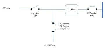
Yes, you would need to move the IQ gateway power supply, it is also required in Enphase IQ8/IQ system controller 2 installations to maintain power to the gateway if the PV relay opens. If you use a separate IQ gateway breaker on the load bus side, then PLC needs to extend across the load bus.
Using DIN rail panels for IQ AC combiner makes it much simpler to add/change/remove DIN rail components.

Enphase IQ Combiner PLC Filter.jpg
If the IQ gateway is co-located in the AC combiner or if connections to PV combiner L1 and L2 are short then PLC carrier communications are not attenuated by much. The closer the IQ gateway L1/L2/N lines are to the inverter the more they'll get attenuated by symmetric EMI filtering.
I use the IQ gateway L1, L2, L3, N circuit as a reference design: MOV's on L1, L2, L3 to N for spike protection, MOV's do not impede PLC carrier communications, no capacitors between L1, L2, L3 and N, PLC transformer in L2, MKT capacitor to bridge L1 PLC carrier to PLC transformer on L2.
 
Last edited:
I think long term, solar has the best overall economic efficiency in terms of operating cost to charge. Also gas or propane is probably goint up in price and solar is also a good hedge against inflation.
Of course, but when there is low solar irradiation and no grid power, you need some other form of backup. And a generator with a 48VDC output has the highest overall efficiency to charge the backup battery, and you do not even need an inverter generator for this.
 
Last edited:
Back
Top