diy solar

diy solar

Hankzor JK BMS with screen and power button

You don't need to set an address: both BMS will show up as a different com port/tty.
I guess, if you connect it to Rpi but if you connect it to another rs485 port (on an inverter for example) each bms would need to advertise an address as per attached protocol description.

Does attached protocol description resemble anything JK BMS uses? I hope it should be universal or very similar? Maybe it would be useful to you somehow too...

Cheers,

A
 

Attachments

  • (LIB) BMS 485 communication protocol 20201208.pdf
    947.6 KB · Views: 105
You can find a list of documentation and protocol for the JK here:

I've written a small implementation of the protocol for integration with Grafana here:

It's not the same as the one you attached to your comment. I believe there is something resembling an address, but I don't remember since I never used it. That said, I don't think you should expect to be able to plug this BMS directly into the inverter. I've asked at some point if they could release the firmware source code, and I know they're looking into it. That way, we could write our own implementations and make it compatible with anything. No idea when though...
 
Ok, update time. Finally had some time to have a look at the new BMS.

View attachment 81464

The new one on the right, old one on the left. They're both 100A versions to keep the comparison easier. The port to the right of the GPS/RS485 label is the display port. As Dave Jones would say: "Don't turn it on. Take it apart!"


View attachment 81465
New one on the right again. The original is hardware version 6.0, the new one 8.0. There have been a few changes, mostly on the other side of the board. The main change on this side of the board is the micro controller. The old version had an original STM32F103; probably due to shortages or because more resources were needed, it is replaced with a GD32F103. This is a pin compatible clone of the STM, it's used on some Bluepill boards and finds its way into many products these days since it's cheaper and actually available, unlike the STM. It also has more RAM/FLASH and can run at higher clock speeds. I'm actually surprised they didn't have the GD32 on there from the beginning. The MOSFETs are still the same: G042N10.


View attachment 81466
The GD32.

View attachment 81467

Other side of the board. More profound changes here. For one, the Bluetooth module was changed. Didn't look at the details, but they're both common modules. The chip at the bottom is a YD3082, which is an RS485 transceiver, which is what is driving the display. I'm not sure yet if this shares the same RS485 bus where one connects the RS485 dongle to. I'll find out later. There are also some added digital isolators that weren't there before (an 122U31) - probably to provide better isolation between the power and control side.

View attachment 81469
The YD3082 RS485 transceiver in the middle to the right.

This is the Display itself. It's very clear and bright, and the power button on the side works fine to turn the BMS on. I somehow wish it could be used to turn the BMS off again, but that's not a deal breaker. Ignore the 6.6V and state of charge, I just connected the BMS to two spare cells and a power supply.

View attachment 81470

I originally wanted to create a custom enclosure for it, but the handle bar mount can be removed easily, and it looks much better this way.

View attachment 81471

Of course, I also opened the display:

View attachment 81472
It's based around a Holtec HT1621 display driver on the right. This thing has a serial interface, and the other chip to the left is a hk32f030, another microcontroller that takes the incoming data and talks to the Holtec chip.

View attachment 81474
The LCD display itself.


I want to dig in deeper in some of the changes and other aspects of the BMS. For one, I really want to figure out how the power button is implemented, and if this is a software or hardware thing (or both). I don't know when I will have time for this though; now that I have one sitting on my desk I want to get back to the RS485 communication, finishing my Grafana interface and then go to the next step: implement a supervisor which has a full overview of all components and their status, and can make decisions based on this...
Very detailed description. This display is a transitional device, which is only for the installation of electric bicycles, and the configuration switch is convenient for customers to activate. In April, a wireless Bluetooth display will be sold together with the 4S BMS. Please contact me and I will give you a new display. Thank you for your support
 
The display size is 4.3 inches, which is suitable for all jkbms. However, if the display is used to connect to BMS, the mobile phone will not be able to connect to BMS.
By the way, do you have any suggestions for the display screen?
 
I like the wired display because it has a power button. True, you don't need it very often, but it's very convenient for those times when you do. Since the way the button works is only a 1K pull down on two pins on the display interface, it's easy to add your own button now without the display. This would go very well in combination with the Bluetooth display, since one of the issues I have with the current display is that it uses too much power even when the display is not showing anything. One of the things you could offer is a button only (and preferably one that can turn the BMS off as well), to make this easier for people that can't make their own. They can then decide if they want the BT display as well, or just the power button functionality.
 
I like the wired display because it has a power button. True, you don't need it very often, but it's very convenient for those times when you do. Since the way the button works is only a 1K pull down on two pins on the display interface, it's easy to add your own button now without the display. This would go very well in combination with the Bluetooth display, since one of the issues I have with the current display is that it uses too much power even when the display is not showing anything. One of the things you could offer is a button only (and preferably one that can turn the BMS off as well), to make this easier for people that can't make their own. They can then decide if they want the BT display as well, or just the power button functionality.
1645354891957.png
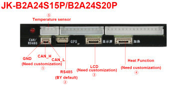
Sweet, 1kOhm pull down should be easy. (It seems as they have modified the BMS once again, added Heat Function and new connectors)
As always a few questions if you don't mind ;)

1. Which PINs are used with the pull-down R on LCD Header?

2. Are those Micro JST GH 1.25mm 3P, 6P & 7P type connectors? (need to buy crimped cables now)

3. Could you confirm if GPS is a JST ZH 4P 1.5mm? (need a cable for RS485 to USB adapter)

4. Any idea how to interface with that Heat Function and is it included with new units or you have to pay extra?

Thank you so much!

A
 
1. Which PINs are used with the pull-down R on LCD Header?

2. Are those Micro JST GH 1.25mm 3P, 6P & 7P type connectors? (need to buy crimped cables now)

3. Could you confirm if GPS is a JST ZH 4P 1.5mm? (need a cable for RS485 to USB adapter)

4. Any idea how to interface with that Heat Function and is it included with new units or you have to pay extra?

1. https://diysolarforum.com/threads/hankzor-jk-bms-with-screen-and-power-button.33267/post-432734

2. I believe so, but don't quote me on that.

3. I will verify this as soon as I can

4. My version didn't have the heat function connector. Need to find one...
 
The display size is 4.3 inches, which is suitable for all jkbms. However, if the display is used to connect to BMS, the mobile phone will not be able to connect to BMS.
Do you mean a mobile phone cannot connect via bluetooth to the BMS while the display is connected to the BMS? That would be terrible.
 
When the monitor is linked to BMS, you need to disconnect the monitor to reuse the Bluetooth linked mobile phone, which is more convenient for battery pack manufacturers. For personal use, we still recommend using the display with link line, thank you
I am not sure I follow your meaning. please tell me if I have it correct.
  1. The monitor can be linked to the BMS by Bluetooth which would disable the Bluetooth app.
  2. The monitor can be connected to the BMS by the wired connection to the "display" port which would enable the Bluetooth app to work at the same time that the LCD display is working.

Yes, two options:

- Bluetooth Display
- Wired display

- Connect the Bluetooth display, can't connect with the app anymore
- Connect the Wired Display, app still work fine
 
Loving the idea with the pulldown resistor to turn on the bms. cant wait to hear how your further exploration pans out. are you planning on putting it together with a two pin connector ommiting the other 4 pins with the resister and button soldered in line?
 
Loving the idea with the pulldown resistor to turn on the bms. cant wait to hear how your further exploration pans out. are you planning on putting it together with a two pin connector ommiting the other 4 pins with the resister and button soldered in line?

Yeah, my plan is to just connect two wires to an appropriate 6 pin JST connector and plug that in instead of the display. I'm thinking of not using the display at all at this time.
 
Yeah, my plan is to just connect two wires to an appropriate 6 pin JST connector and plug that in instead of the display. I'm thinking of not using the display at all at this time.
fantastic work around, very clever! If it goes according to plan i will probably steal your idea ;) haha awesome work. I see your from northern finland. I was in Kuusamo a couple years back, fantastic part of the world! Kippis
 
Kuusamo is nice, Lapland in general is; sadly I don't have much time to go there often. I'll post here when I know for sure the switch thing I mentioned is correct (I mean, I know it is, but I just want to have it as a stand alone switch and have a picture).
 
Update on the power button: for some reason the switch uses the diode of an opto-coupler between between switch and connector. Of course, I've tried just shorting the two switch contacts, and this turns the BMS on as well - but maybe not ideal long term. We could add a diode in the circuit just to mimic the switch in the screen, or put a resistor (1K or something) instead - this should work too. I tried with both a 100K resistor and 1N5819 diode that were on my desk and the BMS turns on in both cases.

The schematic:

Code:
# Display Connector at BMS, R = RED, B = BLACK on the switch cable
┌─────── ─────── ───────┐
│                       │
│ O   O   O   O   O   O │
│ R   B                 │
└───────────────────────┘


 B
 |
 |
 \-->  (button, momentary normal open)
 |
 |
 -
 V  --> diode
---
 |
 |
 R
 
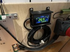
If anyone is interested, I designed a panel mount for the Display that can be 3d Printed. My display came with my JK-B2A8S20P and looks identical to the ones that UpNorth showed pictures of earlier in the thread.

I also discovered that my display will, indeed, turn off the BMS with a long 5(ish) second press of the button.

Model on Thingiverse
https://www.thingiverse.com/thing:5331287

2022-03-26T08:44:04_Davinci_IMG_2114.JPG
 
Back
Top