diy solar

diy solar

My adventures building a Zinc-Iodine battery

With all my recent work in flow batteries in the Zn-I system, I decided to take a new look into Zn-I batteries. In particular a few new papers on back-plating of Zn exist, which is an interesting geometry solution to the problem of dendrite formation. I had never tried it before because I lacked a practical way to achieve it, but now I think I have a potential solution.

See this nature paper (https://www.nature.com/articles/ncomms11801) for more on the backplating configuration. It seems if we can do backplating of Zn in a Water-in-salt-electrolyte (WISE) configuration (https://onlinelibrary.wiley.com/doi/full/10.1002/ange.201909324), we could have a battery that could be rid of the dendrite issue while still providing the benefits of solid formation in the anode, avoiding all I3- formation.

I used the WISE electrolyte on my post successful trials in this thread but I could never get rid of the Zn dendrite problems.
 
Wow you've done a lot since I've last read your ZnBr thread.
With regards to dendrites two ideas come to mind, Redflow does %100 depth of discharge cycles to help prevent dendrites.
Another is a more rigid barrier. perhaps a neutral plate between the cathode/anode would force the dendrites to grow around the obstacle, similar to the backplate idea. or a porous ceramic material (that's obtainable) I haven't found anything yet.
I wonder if just stopping every 50 cycles and fully discharging the cell to 0v could help effectively prevent long-term dendrite growth (its a lot simpler then additives).

https://www.sciencedirect.com/science/article/pii/S2666386422000947 - i have zero idea if this would survive the WIS electrolyte environment.

I do love this back-plating idea. super curious.
Best of luck, i cant wait to see your results and thanks for taking the time to share your results with the community.
 
Last edited:
Wow you've done a lot since I've last read your ZnBr thread.
With regards to dendrites two ideas come to mind, Redflow does %100 depth of discharge cycles to help prevent dendrites.
Another is a more rigid barrier. perhaps a neutral plate between the cathode/anode would force the dendrites to grow around the obstacle, similar to the backplate idea. or a porous ceramic material (that's obtainable) I haven't found anything yet.
I wonder if just stopping every 50 cycles and fully discharging the cell to 0v could help effectively prevent long-term dendrite growth (its a lot simpler then additives).

https://www.sciencedirect.com/science/article/pii/S2666386422000947 - i have zero idea if this would survive the WIS electrolyte environment.

I do love this back-plating idea. super curious.
Best of luck, i cant wait to see your results and thanks for taking the time to share your results with the community.

Thanks for posting!

Doing deep discharge cycles works to some extent but it doesn't really solve the problem fully.
 
I have done some first tests using the following architecture:

1696877833176.png
Basically strips of copper tape are first placed on a square of PE sheet, then a copper tape disc (sanded to a clean surface) and grafoil strip are placed on the anode and cathode sides respectively. A carbon felt is then glued to the grafoil's corners to secure it in place, the copper tape disc adheres using its adhesive. All exposed conductor surfaces are then insulated using nail polish to prevent any electrochemical behavior except for on the carbon felt and the copper disc anode. I used a 20m ZnCl2 + 5m NH4I solution (I ran out of potassium iodide, so I used ammonium iodide for the test). This is a Water-in-salt electrolyte (WISE). The setup is fully immersed in around 2mL of the solution.

As you can see, the above geometry ensures the Anode doesn't face the cathode and there are no direct paths for dendrites to cause a short. They would need to grow all around the electrolyte to achieve that.

I did a couple of cycles at a current density of around 2mA/cm2, charging to 0.5mAh and discharging to 0.7V. The results are promising:

1696878616978.png

The Coulomb efficiency is quite high, above 90%, so we definitely do not get any major soluble triiodide formation in the electrolyte. All the iodide seems to plate as elemental iodide in the carbon felt (in agreement with published WISE results using KI+ZnCl2).

The loss in energy efficiency from the distance between the electrodes also seems to be limited, thanks to the high conductivity of the WISE electrolyte, even though the distance from anode to cathode is quite large as you need to go all around the PE sheet. Plating on the copper electrode looks very regular, at least from a first glance. There aren't any discernable dendrites at this state of charge (SOC). Note that higher EE value are likely achievable when charging at lower current density.

Note that the theoretical energy density you could get from this electrolyte is around 134 Ah/L (around 160 Wh/L at 1.2V) . For reference lithium iron phosphate is normally at around 220 Wh/L. The volume of the cathode material used is 0.26mL, so I would expect the cathode to hold 35mAh at a max.

A battery with this type of backplated configuration cannot be easily rolled, so likely instead of going for very fine separators and high voltage efficiencies a battery like this would work more like a lead acid battery, with larger cells stacked in rows. Basically arrays like the one I showed above stacked together to fill a box with the electrolyte then poured over to fill all the space and fill all the felt (which might require some vacuum to fully achieve wetting of the entire all the surface area.

I am now cycling this battery to 25mAh, which will take a long time per cycle, but I just want to see if it reaches the capacity and how dendrites behave at high SOC.
 
I have done some first tests using the following architecture:

View attachment 171505
Basically strips of copper tape are first placed on a square of PE sheet, then a copper tape disc (sanded to a clean surface) and grafoil strip are placed on the anode and cathode sides respectively. A carbon felt is then glued to the grafoil's corners to secure it in place, the copper tape disc adheres using its adhesive. All exposed conductor surfaces are then insulated using nail polish to prevent any electrochemical behavior except for on the carbon felt and the copper disc anode. I used a 20m ZnCl2 + 5m NH4I solution (I ran out of potassium iodide, so I used ammonium iodide for the test). This is a Water-in-salt electrolyte (WISE). The setup is fully immersed in around 2mL of the solution.

As you can see, the above geometry ensures the Anode doesn't face the cathode and there are no direct paths for dendrites to cause a short. They would need to grow all around the electrolyte to achieve that.

I did a couple of cycles at a current density of around 2mA/cm2, charging to 0.5mAh and discharging to 0.7V. The results are promising:

View attachment 171521

The Coulomb efficiency is quite high, above 90%, so we definitely do not get any major soluble triiodide formation in the electrolyte. All the iodide seems to plate as elemental iodide in the carbon felt (in agreement with published WISE results using KI+ZnCl2).

The loss in energy efficiency from the distance between the electrodes also seems to be limited, thanks to the high conductivity of the WISE electrolyte, even though the distance from anode to cathode is quite large as you need to go all around the PE sheet. Plating on the copper electrode looks very regular, at least from a first glance. There aren't any discernable dendrites at this state of charge (SOC). Note that higher EE value are likely achievable when charging at lower current density.

Note that the theoretical energy density you could get from this electrolyte is around 134 Ah/L (around 160 Wh/L at 1.2V) . For reference lithium iron phosphate is normally at around 220 Wh/L. The volume of the cathode material used is 0.26mL, so I would expect the cathode to hold 35mAh at a max.

A battery with this type of backplated configuration cannot be easily rolled, so likely instead of going for very fine separators and high voltage efficiencies a battery like this would work more like a lead acid battery, with larger cells stacked in rows. Basically arrays like the one I showed above stacked together to fill a box with the electrolyte then poured over to fill all the space and fill all the felt (which might require some vacuum to fully achieve wetting of the entire all the surface area.

I am now cycling this battery to 25mAh, which will take a long time per cycle, but I just want to see if it reaches the capacity and how dendrites behave at high SOC.
What color nail polish works best? Wait, that wasn't my question....

Are both the grafoil and the carbon felt part of the cathode? Would it work the same with just one or the other?
 
So is the the graphite foil and carbon felt the membrane or the polyethylene sheet? Or do they work together and the membrane?

Did you change from matte photo paper?
 
A battery with this type of backplated configuration cannot be easily rolled
I agree it's an unfortunate downside, Im extremely excited to hear that the EE is still high, WIS sounds like a winner to me.
It shouldn't be too hard to stack cells It would be interesting to see if the cell could have a carbon felt on both sides so that during assembly the felt creates some voids for electrolyte. long term I wonder if this stacking would remain balanced over a large number of cycles, like a lead acid. but that's really a question for way down the road.
 
So is the the graphite foil and carbon felt the membrane or the polyethylene sheet? Or do they work together and the membrane?

Did you change from matte photo paper?

This is a different device, not a flow battery but just a regular static battery. There is no membrane here. For updates on the flow battery please check out the flow battery thread!
 
Last edited:
What color nail polish works best? Wait, that wasn't my question....

Are both the grafoil and the carbon felt part of the cathode? Would it work the same with just one or the other?

Haha, I have tried only purple.

About the grafoil. Both are part of the electrode. Although the grafoil is just the exposed current collector. The felt is needed as you need the surface area for the iodine to deposit on. The capacity of the cathode will be limited if the surface area is not enough to support the amount of iodine that has to be deposited.
 
I agree it's an unfortunate downside, Im extremely excited to hear that the EE is still high, WIS sounds like a winner to me.
It shouldn't be too hard to stack cells It would be interesting to see if the cell could have a carbon felt on both sides so that during assembly the felt creates some voids for electrolyte. long term I wonder if this stacking would remain balanced over a large number of cycles, like a lead acid. but that's really a question for way down the road.

You cannot do felt on both sides as felt is not really good for depositing zinc. The Zn starts forming dendrites over the surface of the felt which actually can go all the way around with time since the felt is taller. With a flat metal electrode as anode the Zn deposits are actually much better defined and dendrite growth, while still present is much much smaller. Between the Zn electrodes you would need to put some traditional separator.

The paper on back-plating suggests 1mm of separator spacing per anode, so you would need 2mm of separation between two anodes in a stacked configuration. Filter paper should be an adequate separator for this WISE electrolyte.
 
Last edited:
I have made a pouch design with the above structure to test a more realistic configuration. I made it with an area of 2.5cm x 2.5cm = 6.25cm2 using the same overall structure as shown before. Anode is made of copper and cathode is carbon felt over grafoil. The pouch and insulating separator are made of PE. I also put two layers of kitchen paper over the anode to ensure it has enough spacing. I sealed the entire pouch except for a small opening I used to fill with the 20m ZnCl2 + 5m NH4I electrolyte.

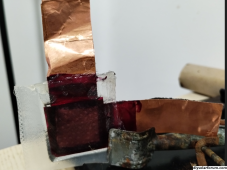
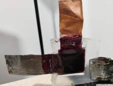
This is the anode side (you can see the copper surface through the wet) kitchen paper.

1696944932369.png

Here is the cathode (you can see the carbon felt)

1696945047055.png

The cell was filled with around 4.5mL of solution, then sealed with hot silicone. The max possible capacity should be around 600mAh.

I am still running the test to 25mAh on the "proof of concept" tiny device, I'll start testing this cell as soon as the test with the small one is done.
 
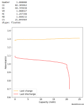
Result of a single cycle on the "proof of concept" 1cm2 device. Charged to 25mAh. There was an abrupt loss of voltage at around 20mAh, so probably something unexpected happened. I will get this device out of the solution and take a look at how it evolved through this high SOC cycle. However no dendrites happened at all, as expected from the backplating configuration.

1696953365659.png
 
Last edited:
I have made a pouch design with the above structure to test a more realistic configuration. I made it with an area of 2.5cm x 2.5cm = 6.25cm2 using the same overall structure as shown before. Anode is made of copper and cathode is carbon felt over grafoil. The pouch and insulating separator are made of PE. I also put two layers of kitchen paper over the anode to ensure it has enough spacing. I sealed the entire pouch except for a small opening I used to fill with the 20m ZnCl2 + 5m NH4I electrolyte.

This is the anode side (you can see the copper surface through the wet) kitchen paper.

View attachment 171657

Here is the cathode (you can see the carbon felt)

View attachment 171658

The cell was filled with around 4.5mL of solution, then sealed with hot silicone. The max possible capacity should be around 600mAh.

I am still running the test to 25mAh on the "proof of concept" tiny device, I'll start testing this cell as soon as the test with the small one is done.

Sadly it was an epic fail ? Some of the nail polish peeled off and huge dendrites grew at the interface between the current collector and the PE. I likely need to do much more diligent cleaning of surfaces before applying the coatings.
 
I repeated the entire process of building the pouch cell and tried charging it. The overpotential is now massive, even at a current of 0.4mA/cm2 the starting charging potential is already above 1.6V, at the same current density as the proof of concept cell the potential is 2.3V ? .

In hindsight it is pretty obvious why. The overpotential is proportional to the average minimum distance between the anode and the cathode, since the cell is now 2.5cm x 2.5cm there are now points inside the anode/cathode that are much further away from the other electrode, greatly increasing the average minimum distance.

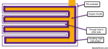
This means that a practical backplating configuration needs to have its smallest dimension be shorter than 1cm (as I already verified the overpotential is low enough with this size), so that the average minimum distance can stay very low, so that the energy efficiency can be high enough. If you build plates, then you need to have holes to allow for the electric field to form between the anode and cathode. Like in the image below for the anode side (the reverse would be the same but with grafoil and carbon felt):

1697049710854.png

It isn't too complicated but I believe the easiest thing to build is going to be a single one of these "teeth". Basically a pouch battery that is 6cmx1cm instead of 2.5x2.5cm. This should demonstrate the increase in surface area without, hopefully, a drop in efficiency. If that shows adequate capacity then the following battery would be a pouch cell with a configuration as shown above. Although the above would likely have a much larger area.

In practice the insulating mask wouldn't be nail polish (that's just easy in DIY) but an acrylic paint applied with a stencil.
 
Does the surface area of the copper anode need to match the available area of the carbon felt cathode? Maybe 1:4 to match the molar densities of the electrolyte?
 
Does the surface area of the copper anode need to match the available area of the carbon felt cathode? Maybe 1:4 to match the molar densities of the electrolyte?
No, the surface area of the copper anode is indeed much smaller than the surface area of the felt, by a factor of perhaps a thousand or more. The felt is a very porous conductive solid, while the copper is a simple flat surface. The difference is that the zinc can deposit over zinc while iodine isn't conductive so any iodine that deposits requires new surface area to effectively deposit without a drop in conductivity.

The main problem of the backplating configuration is related with the distance between the electrodes, more than the conductivity or area of the electrodes themselves.
 
I don't think I will play with this backplated configuration anymore. It is too hard to make because basically any mistake in the entire assembly or any deterioration of the insulating coating means you will get dendrites that will short the battery. It is a very difficult to engineer approach because any mistake is a failure mode. Seems for Zn-I it's back to flow batteries, at least until a good way to get rid of dendrites comes to light.
 
I don't think I will play with this backplated configuration anymore. It is too hard to make because basically any mistake in the entire assembly or any deterioration of the insulating coating means you will get dendrites that will short the battery. It is a very difficult to engineer approach because any mistake is a failure mode. Seems for Zn-I it's back to flow batteries, at least until a good way to get rid of dendrites comes to light.
Have you see this video?
It covers dendrites and how to control their formation with clay
 
Back
Top