I've gotten confused using the Renogy and other wire sizing calculators and seem to get conflicting answers, so I'm hoping someone here can possibly know this off the top of their head. Here's my setup: I've got the Renogy DCC50S (50A DC-DC charger/ MPPT charge controller). I'm installing two 200 watt mono 12V panels on the RV roof (flat) and doing so as parallel. Individual panel specs are: Vmp=20.31, Voc=24.35, Imp=9.85A, Isc=10.33A. At the VERY most, the wiring run from the farthest-most panel to the MPPT will be 30 feet.
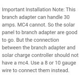
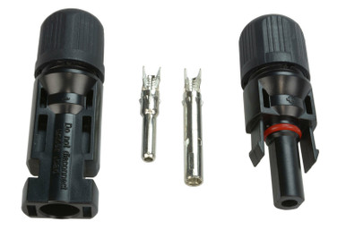
Two questions: What size AWG solar/copper wire should I use from the MC4 (1x2) junctions to the MPPT and what should the fuse size be that I suppose will be installed inline on the positive leg after the two panels are joined and before the controller.
Two questions: What size AWG solar/copper wire should I use from the MC4 (1x2) junctions to the MPPT and what should the fuse size be that I suppose will be installed inline on the positive leg after the two panels are joined and before the controller.