diy solar

diy solar

Safe Grid Use of the 5000ES and transformer

Will, you mentioned issues with MPP similar to the US vs non US models.

Is there more behind this? Ie, only buy MPP unites from certain vendors (watts247?) and not others (directly from MPP?) Thanks.
Good question. MPP has an awful website, but the manuals are straightforward, accurate and updated. The wiring configurations are also consistent. If MPP states that a unit is for north America, it will work for north America.

Watts247 sells European inverters, but he labels each one clearly. Signature solar has been selling the 5000US and labeling it as the 5000ES for a while now, and only until very recently did they present a wiring configuration diagram.
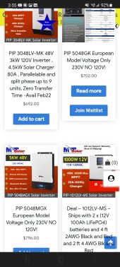
Screenshot_20220124-155557_Chrome.jpg
See how each European specific inverter is labeled? This basic clarification helps a lot.
 
His video was linked to in Post #195 also. It was video describing in detail the safety concerns with the Growatt 5000ES model inverter and split phase transformer. Same thing this thread is discussing. He gave his opinion of why he wouldn't use it, doesn't recommend it. I'm anxious to hear why he took it down.

View attachment 81115
I posted the video without Will's permission after watching it on his channel. That might explain why he took it down?
 
Will, you mentioned issues with MPP similar to the US vs non US models.

Is there more behind this? Ie, only buy MPP unites from certain vendors (watts247?) and not others (directly from MPP?) Thanks.
It seems that growatts sold on eBay and elsewhere are different. But signature solar did not label theirs correctly either. They are saying that growatt did not update their marketing material.

This makes me personally dislike growatt, and I will try to avoid them when possible. Also, signature solar should have posted a wiring diagram and specifically state which model they are selling AND why it is different.
 
It seems that growatts sold on eBay and elsewhere are different. But signature solar did not labels theirs correctly either. They are saying that growatt did not update their marketing material.

This makes me personally dislike growatt, and I will try to avoid them when possible. Also, signature solar should have posted a wiring diagram and specifically state which model they are selling AND why it is different.
Just an FYI, my 5K growatt from SS says "5000 ES" on the product label on the unit

Also, once I order/receive my LV6548's I will crack one of my growatt 5K's open for all those who are curious.
 
This has been a long time thing with solar, mostly because pure off-grid solar was much more widely used internationally of the US, so adapting inverters with auto-transformers was always around. I think it's because of wider usage of homebrew solar as of late, with lots of new people making the jump, that's brought the issue to the surface.
 
Ian of https://www.youtube.com/channel/UCXVNL-mnf_vfD_qT7jLjtcg has one open, I think he is planning a video to show more of it too.

That's the Growatt 12000T (and 6000T), which are based on the Sigineer clone (not the same family of inverter from this discussion)...


Or are you referring to a different video he did (since you had posted the channel link, not to a specific video there)...
 
PS: The open question here is why there isn't a 5000US? The reason that @Will Prowse mentioned sort of is high voltage series strings of panels mainly. I can't find ANY split phase inverter + MPPT with even remotely comparable specs per MPPT and because all of my strings have to be unbalanced because of orientation of number I can have in a given orientation it's super important to get to 400+V. I can't just parallel and use higher amperage without major losses.

Just add another or multiple SCC's. You don't have to run all PV thru the inverter MPPT.
The only other units I can find are either 3 phase (even worse) or require 384VDC battery packs.

If @signaturesolarrichard and Growatt wanted to take the market by real storm they'd use this as an excuse to exchange people their current units with a US version that was split phase and auto-balancing (the math on the EE is straight forward to make this happen, you just have to parallel the fets to handle 100% load on a single leg if necessary, but the fets are really cheap, so it's pretty straight forward to do this. The hard part of the EE is the synchronization of parallel which is the other limiter in the market which is why people are doing this.
 
Read up on auto transformers...

Limitations​

An autotransformer does not provide electrical isolation between its windings as an ordinary transformer does; if the neutral side of the input is not at ground voltage, the neutral side of the output will not be either. A failure of the isolation of the windings of an autotransformer can result in full input voltage applied to the output. Also, a break in the part of the winding that is used as both primary and secondary will result in the transformer acting as an inductor in series with the load (which under light load conditions may result in near full input voltage being applied to the output). These are important safety considerations when deciding to use an autotransformer in a given application.
 
Scroll back through the tread. There are both electrical engineers and certified electricians that have for several months now being telling the world that there is a problem. And there are videos from 3 months ago showing the problem and outlining work arounds and how it doesn't solve the full issue on YouTube. A casual search will find them for you and I'm absolutely sure that this has even been brought up for months in the comments on Poz's video. This isn't new and there is no way for Growatt to have manufactured a transformer that solves a problem before they heard about said problem.
It's been sometime since this thread was started and I know I've known about it for at least 6 months. https://diysolarforum.com/threads/d...pf-5000-es-grid-backup-neutral-bonding.29717/

So, I'm asking, because we're getting marketing people telling us stuff that they have no knowledge of, that Growatt and Signature Solar get real EE people in here that can communicate directly with experts instead of broken telephone. Schedule a live chat somewhere if you want that outlines how to FULLY remediate the problem following the NEC and in an UL listed way. Or outline how you're going to replace the units with units that can meet those criteria.

I don't see how that is at all unreasonable.

And again, if the 5000US is just an ES with the screw removed and nothing else, these units are STILL not UL listable and STILL don't solve the problems as is not the least of which is that at 240V you have to have over 5mm of open air separation at 50 amps or an insulator according to UL regulations.
 
That's the Growatt 12000T (and 6000T), which are based on the Sigineer clone (not the same family of inverter from this discussion)...


Or are you referring to a different video he did (since you had posted the channel link, not to a specific video there)...
Here is his original video:
but talked to him the other day and he seemed to indicate he was going to make a video showing the PCB more.
 
Here is his original video:
but talked to him the other day and he seemed to indicate he was going to make a video showing the PCB more.

Yeah I did see that video the day he posted it, he did show removing the screw, even without taking the board all the way out, it is still pretty obvious there has to be a standoff underneath it... I would be curious to see if Ian could make another video showing full removal of the board (and identify / confirm the standoff under it).

Although it is pretty obvious to me there is a standoff under it. And if that standoff is critical for supporting the board in a significant way, then one might need to install an insulating standoff, like a teflon style standoff w/ teflon screw or something (in its place that is non-conductive), so that it could still provide board support without connecting the board to ground at that location.

At bare minimum I would at least think it would be best to remove the standoff altogether, reinstall the board to check if it flexes too much without having a standoff under that point and decide if needed to install an alternative non-conductive standoff in its place.
 
Last edited:

Well it looks like there are standoffs there (surprise), if you watch Ian's video (14:32), you can roughly guesstimate which one it could be based on these 2 videos (16:45 in last video), the standoff a bit higher than center, and left of center.
 
Last edited:
And I am suppose to believe you vs the #1 seller of inverters in the world A industrial master electrician and a master electrician with no reason to lie?
And you also believe that the chassis not needed to be grounded per you conversation with SS?


Tony Scott

Solar Enthusiast​

Is that the final version of the diagram?
It is still not safe if L1 or L2 make contact with the chassis.
Read more about it here:
diysolarforum.com

Safe Grid Use of the 5000ES and transformer

As shown, if a fault develops in a GroWatt (or AC In panel, or AC Out panel, or Load panel), and "L1" shorts to chassis, chassis of all those devices goes to 120VAC. The only path back to utility meter is through the earth. Your added ground rod is at 120VAC, ground rod by utility meter is zero...
diysolarforum.com
diysolarforum.com
Click to expand...
That's what they told me today and they stated the Chassis do not need to be grounded.
 
Back
Top