You are using an out of date browser. It may not display this or other websites correctly.
You should upgrade or use an alternative browser.
You should upgrade or use an alternative browser.
Solar house generator I started DIY back in 2000 - My path from Trace to Xantrex (on FLA battery) to XW Pro inverters on Tesla Model S batteries
- Thread starter dougbert
- Start date
dougbert
Solar Addict
And chase nipples, use-em!
Ok, I give, what are those? I probably know, but not by that name
dougbert
Solar Addict
I have been playing with the reporting of solar production features of the Schneider Electric "Gateway" box. Yesterday it was a very good sun all-day day. I totally disconnected the grid for some 36 yours and I generated the attached image. My battery SoC was 80% in the morning, yet by noon/1pm my battery was full att 100% during absorption. I measure SoC with a shunt I bought some time ago and does not interface with the Schneider system. It has a separate gauge on my wall.
Current production reduced to just running the house loads. That green line from 12 to 3pm, drops from its peak of 88 amps to the lower values. If there was a place to put that current the arrays would produce up to 100% of capacity, while here I lost that energy
I am in process of making the division load operational, heating an electric water tank, which in turn feeds into my tankless gas water heater. That way I can harvest all the extra lost current into something useful instead of leaving it on the table. Having the ability to measure power and energy and the like, allows for improving the system and reaping greater energy. This chart has a 24 hour time period of data.
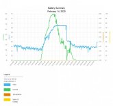
You can see the absorption phase begin around 12pm and then last until 3pm where it drops down to float charge. Then when the sun sets, it is back to battery support for the rest of night.
At 88 amps and 29 volts, that is 2550 watts coming in from the 2 arrays, and it lasted until the battery voltage hit and maintained 29 volts and stabilized. Then the charge controller reduced current, as the absorption phase continued.
The chart measures 4 metrics: current, voltage (on the left of the chart), battery temperature and battery SoC (on the right of the chart). Battery SoC isn't working because I don't have the Schneider shunt installed. The battery temperature is working but not properly reported by the Gateway comm box. That is a bug I am going to report.
This morning my SoC was 70% with slight cloud cover, but the sunshine is getting stronger. I will measure if the SoC can reach 100% by end of day
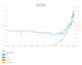
Here is a snapshot of today's charge, from midnight to now, 11am, so just 11 hours of data capture:
dougbert
Current production reduced to just running the house loads. That green line from 12 to 3pm, drops from its peak of 88 amps to the lower values. If there was a place to put that current the arrays would produce up to 100% of capacity, while here I lost that energy
I am in process of making the division load operational, heating an electric water tank, which in turn feeds into my tankless gas water heater. That way I can harvest all the extra lost current into something useful instead of leaving it on the table. Having the ability to measure power and energy and the like, allows for improving the system and reaping greater energy. This chart has a 24 hour time period of data.

You can see the absorption phase begin around 12pm and then last until 3pm where it drops down to float charge. Then when the sun sets, it is back to battery support for the rest of night.
At 88 amps and 29 volts, that is 2550 watts coming in from the 2 arrays, and it lasted until the battery voltage hit and maintained 29 volts and stabilized. Then the charge controller reduced current, as the absorption phase continued.
The chart measures 4 metrics: current, voltage (on the left of the chart), battery temperature and battery SoC (on the right of the chart). Battery SoC isn't working because I don't have the Schneider shunt installed. The battery temperature is working but not properly reported by the Gateway comm box. That is a bug I am going to report.
This morning my SoC was 70% with slight cloud cover, but the sunshine is getting stronger. I will measure if the SoC can reach 100% by end of day
Here is a snapshot of today's charge, from midnight to now, 11am, so just 11 hours of data capture:

dougbert
Last edited:
dougbert
Solar Addict
finally got rid of the red-neck wiring today and got the final circuit from inverter to invert-bypass box which is now in conduit instead of hanging loose. Again took me most of the day.
inverter-bypass opened up and ready for new wire
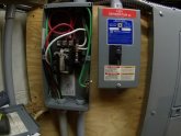
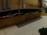
all conduit in now
Notice the orange wire above the service panel. That is 10-3 w/gnd, that is not yet installed but will go over to the water heater as the diversion load
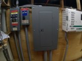
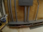
I count 7 circuits now in the gutter raceway in the 6 conduits. The Two output circuits come out and down the big 2" pipe, to the main house panel and the garage.
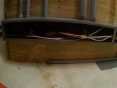
inverter-bypass opened up and ready for new wire

all conduit in now
Notice the orange wire above the service panel. That is 10-3 w/gnd, that is not yet installed but will go over to the water heater as the diversion load


I count 7 circuits now in the gutter raceway in the 6 conduits. The Two output circuits come out and down the big 2" pipe, to the main house panel and the garage.


Last edited:
dougbert
Solar Addict
Battery SoC went from 70 to 88% today even with some clouds. That is almost as good as yesterday where the SoC went from 80 to 100% just with the solar panels and did it in 4 hours. Current reached a high of 98 amps today
Yet, the clouds started to increase by 2PM and really reduced current flow, and graph below shows that. Had to reconnect the grid to get the battery to 100%. Grid AC Bulk stage started at 7PM for 2.5 hours and reached 100% SoC
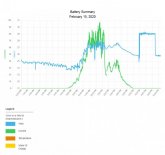
Yet, the clouds started to increase by 2PM and really reduced current flow, and graph below shows that. Had to reconnect the grid to get the battery to 100%. Grid AC Bulk stage started at 7PM for 2.5 hours and reached 100% SoC

Last edited:
pcaballero1959
New Member
- Joined
- Jan 3, 2020
- Messages
- 1
I enjoyed reading every one of these posts. I too was enthralled with the idea of solar independence since I graduated high school in 1978. The initial cost was always too high and I lacked the confidence to try to assemble my own system. I have long dreamed of the day I would retire and see if I can put together a system. I like your view that the grid can be viewed as a source of battery charging. This is a 180 degree fresh view. Also, I liked your observations on cost savings...there are worse things than spending money on a hobby. I recently purchased a Chevrolet Volt. It will never save enough to overcome the cost increase compared to a regular compact gas burner...but I really get a lot of joy from it.
dougbert
Solar Addict
another task completed: The solar Diversion load circuit installed and operational
I got the idea of this from this youtube video
there are several such videos on youtube
When my batteries reach 29.3 volts (per the battery manufacturer for bulk and absorption voltage) my batteries are FULL and current generation drops off. By using my panel charge controller which has an AUX control line that can be programed to go active upon various triggers I can capture that lost power.
So I am using array 1's AUX control line to engage a 12volt relay that activates 2 DC/AC Solid State Optic Relays which enables the AC circuit to start heating the water in the electric water heater
Below is the 12v activated relay with the AUX control line using yellow F type connectors
The low voltage outdoor 12 gauge wire (from HomeDepot in 100 ft segments) runs the POS line through the relay on the nut tightened connectors
This 12 gauge is over doing it, but I have several of these as 12v extension cords I use with HAM radio. This wire sources its power from my 12v solar panel on the roof, again powering my HAM shack.
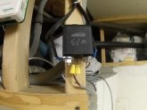
Here another shot of the 12v relay ($12 at Amazon https://www.amazon.com/gp/product/B07T35K8S2/ref=ppx_yo_dt_b_search_asin_title?ie=UTF8&psc=1)
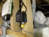
Here the 12g wire connects to the Solar Panel input side of the Morningstar controller. Connecting it this way, there is power ONLY when the sun shines, when I want it. This way during the nighttime grid battery charge, it won't enable the water heater load
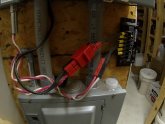
Here is the "orange" 10-3w/grd wire I showed earlier, connecting to the service panel. It currently will be driven by a 15 amp breaker @ only 120v since that is all my inverter is. Thus, using the 4000watt heater element, it will only consume 1000watts of solar panel power.
here is a link for various parts plus the math on that http://waterheatertimer.org/How-to-wire-water-heater-for-120-Volt.html
Later with the new inverter, I will move it to a 20 amp 240v breaker, and install 2 2000watt AC heater elements
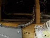
here are the 2 SS-Relays. Orange wire incoming power, and the armored wire running to the electric header, the other end in visible in the left foreground
The 12v black outdoor wire comes in the bottom of the SSRs. I am going to put a plexiglass cover over this, so the lights on the SSRs will be visible when active.
SSR Source: https://www.amazon.com/gp/product/B0749JYKY8/ref=ppx_yo_dt_b_search_asin_title?ie=UTF8&psc=1
Heat Sink: https://www.amazon.com/gp/product/B07C8R7MS2/ref=ppx_yo_dt_b_search_asin_title?ie=UTF8&psc=1
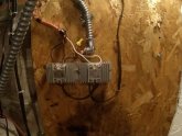
Shot of the water heater (with the Milwaukee battery charger on top) and the SSRs in the upper right
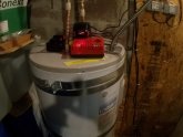
Here is a shot of the cold water line line (foreground left) and the hot water return line (foreground right) I just installed as well. Currently only one heater is install, but I have 2 heaters(left over from the thermal solar water heater project) and plumbed things so I can put 2 water heaters in series. I have a temp gauge on the hot water out line prior to the actual tankless gas water heater IN line, so I can read the temperature gain of the PV heater. Water currently is 45 F, anything higher than that is PLUS
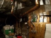
My house was built in 1930 and had a crawl space. I spent 8 years digging a basement, 16'x30' paying neighborhood young men, 50 cents per 5 gallon bucket of dirt and rock that they would haul up and out. I know somewhat dumb, but recovering from a divorce, cash flow was low to buy a real house with a basement. We had this one and we continue to improve what we have. Getting close to paying OFF the mortgage.
Anyway, the diversion load system is very appealing to me and I will report how it works and how warm the water gets. 1000 watts isn't much, but right now when the battery is full, I have no where to send the solar current. Later with larger arrays, a larger 240v inverter, 2000 watt heater should work well
dougbert
I got the idea of this from this youtube video
there are several such videos on youtube
When my batteries reach 29.3 volts (per the battery manufacturer for bulk and absorption voltage) my batteries are FULL and current generation drops off. By using my panel charge controller which has an AUX control line that can be programed to go active upon various triggers I can capture that lost power.
So I am using array 1's AUX control line to engage a 12volt relay that activates 2 DC/AC Solid State Optic Relays which enables the AC circuit to start heating the water in the electric water heater
Below is the 12v activated relay with the AUX control line using yellow F type connectors
The low voltage outdoor 12 gauge wire (from HomeDepot in 100 ft segments) runs the POS line through the relay on the nut tightened connectors
This 12 gauge is over doing it, but I have several of these as 12v extension cords I use with HAM radio. This wire sources its power from my 12v solar panel on the roof, again powering my HAM shack.

Here another shot of the 12v relay ($12 at Amazon https://www.amazon.com/gp/product/B07T35K8S2/ref=ppx_yo_dt_b_search_asin_title?ie=UTF8&psc=1)

Here the 12g wire connects to the Solar Panel input side of the Morningstar controller. Connecting it this way, there is power ONLY when the sun shines, when I want it. This way during the nighttime grid battery charge, it won't enable the water heater load

Here is the "orange" 10-3w/grd wire I showed earlier, connecting to the service panel. It currently will be driven by a 15 amp breaker @ only 120v since that is all my inverter is. Thus, using the 4000watt heater element, it will only consume 1000watts of solar panel power.
here is a link for various parts plus the math on that http://waterheatertimer.org/How-to-wire-water-heater-for-120-Volt.html
Later with the new inverter, I will move it to a 20 amp 240v breaker, and install 2 2000watt AC heater elements

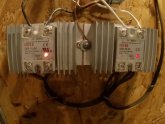
here are the 2 SS-Relays. Orange wire incoming power, and the armored wire running to the electric header, the other end in visible in the left foreground
The 12v black outdoor wire comes in the bottom of the SSRs. I am going to put a plexiglass cover over this, so the lights on the SSRs will be visible when active.
SSR Source: https://www.amazon.com/gp/product/B0749JYKY8/ref=ppx_yo_dt_b_search_asin_title?ie=UTF8&psc=1
Heat Sink: https://www.amazon.com/gp/product/B07C8R7MS2/ref=ppx_yo_dt_b_search_asin_title?ie=UTF8&psc=1

Shot of the water heater (with the Milwaukee battery charger on top) and the SSRs in the upper right

Here is a shot of the cold water line line (foreground left) and the hot water return line (foreground right) I just installed as well. Currently only one heater is install, but I have 2 heaters(left over from the thermal solar water heater project) and plumbed things so I can put 2 water heaters in series. I have a temp gauge on the hot water out line prior to the actual tankless gas water heater IN line, so I can read the temperature gain of the PV heater. Water currently is 45 F, anything higher than that is PLUS

My house was built in 1930 and had a crawl space. I spent 8 years digging a basement, 16'x30' paying neighborhood young men, 50 cents per 5 gallon bucket of dirt and rock that they would haul up and out. I know somewhat dumb, but recovering from a divorce, cash flow was low to buy a real house with a basement. We had this one and we continue to improve what we have. Getting close to paying OFF the mortgage.
Anyway, the diversion load system is very appealing to me and I will report how it works and how warm the water gets. 1000 watts isn't much, but right now when the battery is full, I have no where to send the solar current. Later with larger arrays, a larger 240v inverter, 2000 watt heater should work well
dougbert
Last edited:
dougbert
Solar Addict
The diversion load circuit has been working today for 2.5 hours, since noon. That is when the battery was filled (29.2 v for 10 minutes) and the AUX line went active
here is pic of the 2 SSRs with their ACTIVE lights on
UPDATE: Do NOT use these cheap SSRs that cost $20, they will and did burn up over time. Get the $50+ ones
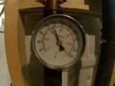
I just measured the temp of the water by disabling the tankless heater and allowed the water to run through the temperature gauge and the water was hot. 115 F hot.
I don't know how much of the 50 gallons is warm, but the top part is
this is exceeding my expectation
dougbert
here is pic of the 2 SSRs with their ACTIVE lights on
UPDATE: Do NOT use these cheap SSRs that cost $20, they will and did burn up over time. Get the $50+ ones

I just measured the temp of the water by disabling the tankless heater and allowed the water to run through the temperature gauge and the water was hot. 115 F hot.

I don't know how much of the 50 gallons is warm, but the top part is
this is exceeding my expectation
dougbert
Last edited:
dougbert
Solar Addict
Today's Total solar generated energy was 16.4 kwh, the highest I have every had.
Last edited:
dougbert
Solar Addict
What is that Anderson PowerPole "doodad" in your third picture?
It looks like one pair of 12AWG wires coming in and two pairs of 12AWG wires going out??
LOL
that is the 12v solar "generator". One of my early projects.
1) 12v solar in going to the morningstar controller. That is where I tapped the power source for the water heater relay
2) line going from the controller to the battery
3) Load from controller going no where
I was thinking of versatility of connections back then and the Anderson seemed good. This the first time I have used them
dougbert
dougbert
Solar Addict
APP’s are good connectors. Just wanted to be sure there wasn’t two loads on one feeder
ok I think I misunderstood your original statement
that red APP connector allows for more than two lines, so the solar panel IN lead connects to the charge controller input and the power line to the 12V power leg on the relay. So I might have two loads on the solar panel.
What would the issue be?
200 watts original panels
low load on the SSRs
ok I think I misunderstood your original statement
that red APP connector allows for more than two lines, so the solar panel IN lead connects to the charge controller input and the power line to the 12V power leg on the relay. So I might have two loads on the solar panel. What would the issue be?
Just current carrying capacity. If you had more load than one source wire could carry I would just double up on the source side.
dougbert
Solar Addict
Just current carrying capacity. If you had more load than one source wire could carry I would just double up on the source side.
oh
200 watts panels - max 12 amps incoming, split between the charge controller and the low load on the SSR control circuit
Pardon my ignorance but you have two pairs of wires on the left side of the doodad. What are those and total amps/volts there?
On the right side of that doodad you have only one pair of wires carrying that total sum of amps/volts. My concern is if the wire can handle the combined amps/volts.
Also, that is 12 awg wire correct?
On the right side of that doodad you have only one pair of wires carrying that total sum of amps/volts. My concern is if the wire can handle the combined amps/volts.
Also, that is 12 awg wire correct?
dougbert
Solar Addict
Pardon my ignorance but you have two pairs of wires on the left side of the doodad. What are those and total amps/volts there?
On the right side of that doodad you have only one pair of wires carrying that total sum of amps/volts. My concern is if the wire can handle the combined amps/volts.
Also, that is 12 awg wire correct?
SOURCE: red/white circuit goes to the 200 watts of solar panels on the roof, max 12 amps @17v
SINK: black pair goes the 12v relay as power source through the 12v black relay. Coil driven by the AUX control line, and then onto the SSR low amp control optic switch.
SINK: right black pair goto the solar input on the charge controller
yes, 12g, had some lying around when I built that years ago
Well according to this:

 www.solar-wind.co.uk
With 12g you should be fine. Just trying to be helpful and I always wonder when I see four wires into two.

DC Cable Sizing Tool - www.solar-wind.co.uk
Free cable-sizing tool to establish the correct size of cable for DC power system cables. Especially important for low voltage, high current systems.
With 12g you should be fine. Just trying to be helpful and I always wonder when I see four wires into two.
dougbert
Solar Addict
The diversion load, heating water @ 1100 watts is working, but does not generate a lot of hot water, yet I expected that to start with.
What has occurred is the daily generation of energy has risen from around 9-11 kwh to now 17-18kwh per day, the past 4 sunny days. The battery SoC is abt 80% at 9AM and rises to 100% in the 11:30am to 12noon time frame, then the diversion load kicks in and amps generated bumps up until the sun goes down.
Looking forward to more panels installed
dougbert
Solar Addict
dougbert
Solar Addict
dougbert
Solar Addict
JeepHammer
Solar Wizard
- Joined
- Nov 15, 2019
- Messages
- 1,149
I don't use this word very often...
AWESOME!
AWESOME!
Similar threads
- Replies
- 23
- Views
- 944
- Replies
- 0
- Views
- 292
- Replies
- 20
- Views
- 1K
- Replies
- 1
- Views
- 216


