A 3 pole neutral switching would be code compliant and actually preferred over a 2 pole non neutral switching in most cases.
From the various discussions in threads here and correspondence with suppliers, manufacturers and engineers, the consensus was having a common neutral like your example was not supported .
A common neutral in the system wired as you have it creates a neutral ground loop in bypass mode. Current will be shared by the neutral circuit in the inverter and also thru the neutral from the transfer switch to the N-G bond at the disconnect or main panel. Whether this creates another possible ground loop path with the input and output grounds tied together thru the inverter depending on circuit resistance and distance to/from N-G bond, I do not know but is possible. This is why a 3 pole neutral switching transfer switch on output with an EGC only run to inverter input is desired.
I did run across this thread which is quite interesting.
https://diysolarforum.com/threads/s...sing-taiwan-based-all-in-one-inverters.41802/
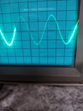
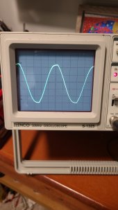
The poster believed the 48V AC charger created the problem as it might be PWM based. This might actually be the case if charging is set to be split between solar and AC input. It could also be a result of using a common neutral with grid bypass wired in. Just thought I'd throw that in considering you saw a cleaner waveform with PV connected.