diy solar

diy solar

What would a difference in bus bar resistance do?

cinergi

1.21 Jigawatts
Joined
Aug 9, 2020
Messages
1,419
I just did a capacity test on my 16s 280ah bank and cell 9 hit low well before the others (robbing me of about 28ah of capacity). I don't know if cell 9 is bad or, perhaps, it's because cell 9 is on the other side of my rectangular layout with a MUCH larger copper bus bar coming from cell 8. I'm trying to think through what would happen but it's blowing up my brain so I thought I'd ask here. I just checked the millivolt difference on the bus bars (e.g. cell 6 neg to cell 7 pos) during a 0.43C charge to get an idea of resistance and the big bar is 1.3mv and most of the others are 2.5-2.9 (I have some that are as high as 9mv ... so I'll be going and correcting any of them that are above 3mv) . Anyway ... just wondering if that's perhaps why cell 9 hit 2.5 cutoff well before the others.. was it taking more of the load due to the lower resistance? Or is that just coincidence?

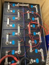
In the picture, the bus bar in question is top-center.
 

Attachments

  • IMG_8881.JPG
    IMG_8881.JPG
    165.5 KB · Views: 32
If you want to stop bending your brain... swap cell 9 with another in the pack and observe. If the problem stays at position 9, bus bar. If not, cell.

....

I wrote a long wordy explanation that used to be here, about bars+cells forming voltage dividers and how that gives an offset for the BMS sense wires, and also affects charging power at each cell, but that one sentence above is the far less brain bending solution. :)
 
LOL. Yeah that's a good idea. Not sure why I didn't think to move the cell to see if the problem followed or stayed. I'm getting tired of disassembling and reassembling my 16s pack :)
 
He gnubie, are you advocating mechanics replacing parts until the car works, then billing the customer for everything? No figuring things out? :)

Yes, swapping to see what the problem follows is a good idea. But if "resistance" was the problem, re-seating a connection could mask it.

OP said 16S. All in series? Series resistance isn't going to rob any pack of its capacity. All will feed identical current, unlike a series/parallel configuration. It could give an altered cell voltage to BMS, since BMS has one wire per busbar, not one wire per cell terminal.

Did the imbalance remain after you stopped drawing current? If so, it isn't resistance.
Would either be cell capacity, or cell balancing.
 
Oh look, I have two identical opaque tinted lamps next to each other in the same fitting and they should both be lit at the same time but only one is. I know, I'll go deep into the theory of operation of the car's electrical system, I'll write a thesis on how incandescent lamps work... and then I'll understand why the lamp isn't lighting... or I could just try switching them and see if I have a blown bulb or not.

Sometimes switching parts is the most appropriate course of action. An intelligent and wise person is capable of making the determination of when it is and isn't.
 
He gnubie, are you advocating mechanics replacing parts until the car works, then billing the customer for everything? No figuring things out? :)

Yes, swapping to see what the problem follows is a good idea. But if "resistance" was the problem, re-seating a connection could mask it.

OP said 16S. All in series? Series resistance isn't going to rob any pack of its capacity. All will feed identical current, unlike a series/parallel configuration. It could give an altered cell voltage to BMS, since BMS has one wire per busbar, not one wire per cell terminal.

Did the imbalance remain after you stopped drawing current? If so, it isn't resistance.
Would either be cell capacity, or cell balancing.

Yup 16 in series. The imbalanced remained after discharge. The cells were perfectly top-balanced to 3.650 as measured at each cell terminal.

I guess high resistance in a single location just limits discharge amperage for the entire pack, but every cell would contribute the same # of electrons? Anyway, we'll find out more as I continue to work on my pack.
Go ahead and try Gnubie's suggestion of swapping packs.

But, current through all cells are identical, unless there is leakage through some path (e.g. BMS)

"perfectly top-balanced"

These things don't have a straight line graph for state of charge vs. voltage. I don't use Lithium ... Is 3.650 on the relatively flat portion? Or after the curve has turned up steeply?
The following link has as graph which appears to show 3.65V is reasonably far up the curve, but just below the knee:


That would allow some error in SoC, but not much if all cells were measured with the same meter to 3 places after the decimal point. And double-checked after resting or a period of time. Check that again, make sure they really reached and remained at same voltage, because due to impedance differences some might have lagged behind in taking charge, if you simply disconnected charger at that voltage.

If they were actually top balanced well, and they are imbalanced after discharge and sitting at rest for a while, then they differ in capacity.
If there were poor contacts between some cells, high resistance, then BMS would have seen low voltage for a cell while others were still holding up voltage.

"Remained after discharge". If they were top balanced, and are now bottom-imbalanced, they differ in capacity. A chain is only as strong as its weakest link, and that's all the Ah your pack can deliver.
 
Thanks @Hedges. 3.650 is the absolute top and end of the knee for LiFePO4. It sat there for several hours before I disconnected the charger with 0.2 amps flowing into the entire array of 16 cells - so I'm sure it was top balanced.

But yeah, I think the conclusion here is that I have a "bad" cell. I'm charging up a spare cell I have now and will swap it out and repeat the test. I'll report further tests and results in my main build thread to keep it consolidated there.

Thanks all!
 
You could always capacity test the cell individually.

I wonder if people get top balance issues by
A) leaving the cells paralleled after reaching the maximum voltage and disconnecting the charger. In that case stronger cells might discharge to feed weaker cells.
B) damaging individual cells by charging out of spec. Spec is to stop charging at 0.05C. Sometimes people get a bloated cell from this that might not have had an issue if it wasn't treated in that way.
 
I will capacity test it after I pull it from the bank. I have one of those capacity tester doo-dads...

I disconnected the cells immediately after I disconnected the charger.

The cells were compressed during the charge.

Significant damage won't occur by bringing the cells up to 3.650 once for a relatively short period of time. I've not seen bloated LiFePO4 cells from charging to 3.650 - only when it's gone higher (doesn't mean it hasn't happened - I just haven't seen that in my travels here).
 
If this one longer bar is 3 times the resistance of the other buss bars, the voltage drop being added to the one cell might cause a small imbalance. But as I think about this, if it was during discharge, it could certainly cause the cell with the extra series resistance to appear to be at a lower voltage. If the short buss bars are all dropping just 0.02 volts, they all look balanced, but the real cell voltage is actually 0.02 higher than the BMS is seeing. Not too big of a deal. But now you have one cell with 3 times the resistance from a much longer buss bar. This cells reported voltage from the BMS leads is lower by 0.06 volts, even though the actual cell voltage is the same as the others. If you move the balance lead to the other end of the extra long buss bar, does the low cell reading move to the cell on the other side of the buss bar? Measure the actual cell voltage under load, and also try to measure the drop across each buss bar. Can you parallel another bar to bring the longer one down to the same voltage drop as the others?

When I wired up my battery bank, I also ran into a position where there is a cable between cell 10 and 11, the rest of the connections are short buss bars. When you connect the wires to the BMS, if you do connect to one end of a longer wire, the cell included with the longer cable or buss bar will have that resistance added. At low current it will not make a real difference, but when you are running at 100 amps, it can cause a substantial difference from the cell next to it. In a perfect world, each cell would be measured just across the cell. But no BMS I have used yet has a pair of wires to go to each cell. They just have a single wire to place between each cell connection. To reduce the error, each cell should also include one buss bar. In a typical 16S setup, you can have them all match except for one of the end cells will not have a buss bar. In my case, I connected the balance wires to the middle of each buss bar. And where I had the cable, I used a pair of wires connected to both ends of the buss bar to get the average voltage equal to the middle of the cable. The 11 inches of #2 wire is hopefully close to the resistance of the short but fairly thin buss bars between the other cells. At up to 80 amps, I did not see a problem, so I think I got the resistance close enough. Or at least all of them are low enough to not add too much error.
 
The low reading remained even after the BMS disconnected - so it was truly low. FYI the long bus bar has less resistance even though it's 1" longer because it's 160mm^2 versus the ~60mm^2 of the provided doubled-up bars.
 
Sounds like you are right and you have an underperforming cell! It's a shame that one costs you that 10% on every one! Good thing you have a spare!!
 
Back
Top