You are using an out of date browser. It may not display this or other websites correctly.
You should upgrade or use an alternative browser.
You should upgrade or use an alternative browser.
Wire size and fusing for 3P array
- Thread starter fafrd
- Start date
FilterGuy
Solar Engineering Consultant - EG4 and Consumers
Yes..... but the requirement has nothing to do with the fuses. The fuses are there to protect the panels on that string. They are not there to protect the output circuit. The NEC wants the wires for the output circuit to handle 1.56 the Imax, where Imax is the sum of the Iscmax of all the parallel strings. With this gauge wire, a short on the output circuit could sit there all day and not cause a fire (and not blow the string fuses)So with 3 incoming 15A fuses rated at 90C, the outbound wire needs to be rated for at least 45A, correct?
Correct, but as with the wire, it is not related to the fuse.But the question of overall triple Y-connector rating remains: if rated for 45A it would be safe protected by 3 15A fuses and if only rated for 40A, it would not (at least according to NEC), correct?
Got it, sorry. So with a 90C rating, it just means an additional safety factor.
Got it - thanks for explaining. So in that case, it means the outbound wire needs to be rated for 3 x 156% x 9.29A = 43.55A, not 3 x 15A = 45A, correct?Yes..... but the requirement has nothing to do with the fuses. The fuses are there to protect the panels on that string. They are not there to protect the output circuit. The NEC wants the wires for the output circuit to handle 1.56 the Imax, where Imax is the sum of the Iscmax of all the parallel strings. With this gauge wire, a short on the output circuit could sit there all day and not cause a fire (and not blow the string fuses)
In any case that triple-Y with 10AWG output wire but only rated to 40A of output current does not look like it will cut it
And so the double-Y which does not require any fusing will be fine with a 2P1S string of my panels because the output only needs to be rated for 2 x 156% x 9.29A = 29.03A, we’ll below their output rating of 40A (10AWG),Correct, but as with the wire, it is not related to the fuse.
FilterGuy
Solar Engineering Consultant - EG4 and Consumers
CorrectGot it - thanks for explaining. So in that case, it means the outbound wire needs to be rated for 3 x 156% x 9.29A = 43.55A, not 3 x 15A = 45A, correct?
Can’t believe it’s taken me 2-1/2 months to circle back to this idea, but I now have a different array I’m planning where a 3P string of different panels I just acquired is once again attractive and would appreciate a reality check from you that I’m understanding everything correctly:Correct
245W panels
Isc @ 50C = 8.782A so need 15A fuse on each panel
60C Isc @ 3P = 26.346A so need OCPD of at least 33A protecting wire rated for at least 41.2A
From our previous discussion, 10AWG 90C PV wire is safe for up to 55A in air as long as all connections are rated for 90V or higher.
So the home run wire from the final Y connector to the roof-mounted junction box can be 10AWG as long as both that final Y connector as well as the connector within the junction box are both also rated for 41.2A or more up to 90C.
If you look at these Y connectors from Staubli, they are rated for 50A up to 90C NEC: https://www.ecs-ecart.com/uploads/1/2/5/4/125454154/sol-branch-connector-mc4-evo-2-11014100-en.pdf
The same document also explicitly shows a 3P string constructed using 3 of these Y connectors.
I already have a DIN-mounted terminal block in my roof-mounted junction box rated for 60A: https://www.amazon.com/gp/aw/d/B07T...d2lkZ2V0TmFtZT1zcF9waG9uZV9kZXRhaWwp13NParams
And that 60A current rating is up to a max operating temperature of 120C: https://www.dinkle.com/en/terminal/DK10N
So I can run 10AWG or 8AWG (depending on voltage drop) from that junction to an MC4 connector rated for at least 41.2A up to 90C of higher.
Staubli’s 8AWG MC4 connector is rated for 70A up to 85C and their 10AWG MC4 connector is rated for 50A up to 85C: https://www.staubli.com/content/dam/spot/SOL-Main-11014092-en.pdf#page=18
So if I use either of those the entire temperature rating drops to 85C which still means 10AWG rated over 50A@80C and 8AWG rated over 70A@80C.
Alternatively, these 8AWG MC4 connectors from BourgRV are rated for up to 65A @ max temperature of 221F / 105C: https://www.amazon.com/dp/B09YM1Y4F...lja1JlZGlyZWN0JmRvTm90TG9nQ2xpY2s9dHJ1ZQ&th=1
So either way, connecting from the junction box to the outbound branch of a first Staubli Y connector with a rating of over 41.2A seems possible.
From there, connecting through a 15A MC4 fuse to the first 245W panel in the 3P string with the other branch connected to a 10AWG MC4 extension cable to a second Staubli MC4 Y connector, each branch of which will connect through another 15A MC4 fuse to a second and third 245W panel completes the 3P string in a way that respects code.
The home run wires from roof-mounted junction box to breaker panel near SCC are 6AWG, so I have no concerns about handling the 26.346A worst-case Isc down to there, but I’d appreciate your reality check that using the Staubli Y connectors and MC4 wires rated for at least 41.2A @ 85C is a safe solution to wire up this 3P array.
FilterGuy
Solar Engineering Consultant - EG4 and Consumers
I am struggling to understand the description of the system.Isc @ 50C = 8.782A so need 15A fuse on each panel
Note: I can't tell how many panels are on each of the 3 parallel strings, but for calculating the wire and fuse sizes it does not matter how many panels there are. It could be 1 panel per string or 10 per string. The current calculations are the same.
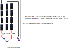
A 3 string array of panels with panel ISC of 8.782A would look like this with in-line fuses and Y connectors:
The same array with a combiner box might look like this:
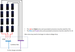
Note that there is only one fuse per string.... no matter how many panels are on the string.
Does this help?
Our earlier discussion was about a 1S3P string and I should have stated that again instead of just saying ‘3P’ assuming you’d remember our earlier discussion.I am struggling to understand the description of the system.
Note: I can't tell how many panels are on each of the 3 parallel strings, but for calculating the wire and fuse sizes it does not matter how many panels there are. It could be 1 panel per string or 10 per string. The current calculations are the same.
A 3 string array of panels with panel ISC of 8.782A would look like this with in-line fuses and Y connectors:
View attachment 123605
The same array with a combiner box might look like this:
View attachment 123604
Note that there is only one fuse per string.... no matter how many panels are on the string.
Does this help?
So my 3-panel string looks like your first picture where each of the 4 panels in series is reduced to just a single panel.
I have a 15A inline MC4 fuse connected to each panel before it connects to the common home run wire using an MC4 Y connector.
I’m charging a 24V battery with a 1S array, so voltages are low and currents are high.
FilterGuy
Solar Engineering Consultant - EG4 and Consumers
OK. That does not change the current calculation.So my 3-panel string looks like your first picture where each of the 4 panels in series is reduced to just a single panel.
I’m charging a 24V battery with a 1S array, so voltages are low and currents are high.
What are the Voc and Vmp of the panels?
Most charge controllers need 4 or 5 volts above battery voltage just to turn on. That means the panel Vmp should probably be at least 36V for a LiFePO4 battery (Preferably a few volts higher). You might get away with Voc of 36V, but that would be pushing it, Particularly on hot days.
Voc = 37.5V @ 25COK. That does not change the current calculation.
View attachment 123659
What are the Voc and Vmp of the panels?
Vmp = 30.2V @ 25C
My Epever SCC has an MPPT range starting at Vbat + 2V.Most charge controllers need 4 or 5 volts above battery voltage just to turn on. That means the panel Vmp should probably be at least 36V for a LiFePO4 battery (Preferably a few volts higher). You might get away with Voc of 36V, but that would be pushing it, Particularly on hot days.
Battery is typically discharged to under 26V overnight, so morning needs to increase to 28V for charging to start (which it should with a Voc of over 37V).
When approaching full charge voltage of over 28V, the SCC will need a string voltage of at least 30V to keep charging, which means it may lose some potential power by operating above Vmp (which is the case anyway since it will be in CV mode).
So I think the charger will start up fie at 1S and if not will fall back to 2S.
Also, just in terms of the wiring diagram, we’re discussing the wiring on the roof between panels and roof-mounted junction box including the junction between those wires and 6AWG home-run wires to the basement.
The + 6AWG home run wire terminates in a 50A breaker before continuing on the the SCC.
And thanks for the confirmation about the 41.1A but in terms of wire guage on the roof, do you agree 10AWG will suffice (subject to voltage drop) or do you see a reason 8AWG will be required (again, freestanding wires in air)?
FilterGuy
Solar Engineering Consultant - EG4 and Consumers
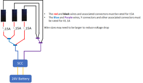
Is this the set-up?
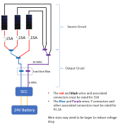
The 6AWG part of the output circuit will be OK.
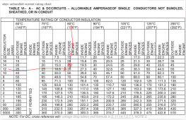
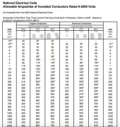
The 10AWG part of the output circuit is marginal. If you go strictly by the NEC chart, 10AWG should not be used for 41.1A even for 90C rated wire. (The limit is 40A for 90C wire.) 8 AWG would be fine.
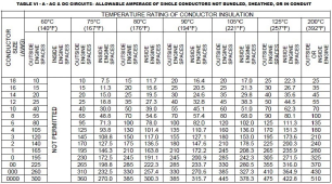
However, if you go by the standard used in boating you are probably OK

The 6AWG part of the output circuit will be OK.
The 10AWG part of the output circuit is marginal. If you go strictly by the NEC chart, 10AWG should not be used for 41.1A even for 90C rated wire. (The limit is 40A for 90C wire.) 8 AWG would be fine.

However, if you go by the standard used in boating you are probably OK

You are a fantastic asset to this Forum!Is this the set-up?
View attachment 123669
The 6AWG part of the output circuit will be OK.
The 10AWG part of the output circuit is marginal. If you go strictly by the NEC chart, 10AWG should not be used for 41.1A even for 90C rated wire. (The limit is 40A for 90C wire.) 8 AWG would be fine.
Yes, that is exactly the circuit I am considering, thank you.
My 6AWG home run wires are in conduit (3-conductors per conduit), so I should apply the NEC code.View attachment 123667
However, if you go by the standard used in boating you are probably OK
View attachment 123668
The PV wires on the roof are freestanding wires in air, so the standard you say is used in ‘boating’ which I’ve also seen described as the ‘chassis wiring’ limits should be able to be safely applied.
The Staubli Y connectors I referenced earlier have an NEC rating of 50A up to 90C, so those are safely over 41.2A.
And those Staubli MC4 connectors for 10AWG are rated for 50A but only up to 85C but that should also be fine.
So as long as voltage drop is not an issue (compounded by my low margin versus the battery voltage), I should be able to maintain all of the PV wiring on the roof at 10AWG.
I’ve already bought the 3 panels for that output circuit and everything from the junction box on the roof through to the SCC is already installed (just need to get the MC4 connectors and PV wires).
The older-generation-but-new panels I got were such a good deal that I’m now planning to pick up another 3 panels.
I can make 2 parallel runs of 6AWG down to the basement so I can install 2 completely parallel output circuits as you have pictured above.
I obviously could connect those two output circuits to two independent and SCCs but I am hoping to connect them to a single SCC.
If I combine the two 6AWG circuits in the DC breaker box after the 2 50A breakers / switches, I just need to assure I’m using wires rated for at least 82.4A from the DC breaker box to the SCC, correct?
Even using the boating / chassis wiring limits, 6AWG at 82A is just barely not going to make it, but 6AWG is the maximum wire size my 60A Epever SCC is designed to handle.
The SCC has a rated power charge power of 1500W at 24V and can never accept more power than than.
Even if the 24V battery discharges all the way down to the BMS cut-off of 2.5V/cell, battery voltage will always be at least 20V meaning incoming PV voltage must always be at least 22V.
1500W / 22V = 68.2A, so incoming current can never exceed that level which is why a 6AWG maximum wire size will suffice.
If there is a short within the SCC itself, it could draw as much as 6 x ISC = 52.7A which can easily be handled by 6AWG.
So I believe I’ll be OK without any OCPD in the DC breaker/combiner box at all using 6AWG, but since I want a switch anyway, I’d like to use one or two breakers both for convenience as well as to have something trip if the SCC ever develops a short.
In normal operation at Vmp of 30.2V, typical max input current will be limited to less than 43A while absolute maximum input current based on panel ratings will be less than 45.7A.
The 50A DC breaker I have currently only provides a 16% margin which is probably too little to avoid nuisance trips under normal operation, while a 60A breaker would give me a 40% margin above typical max operating current and a 30% margin above absolute max operating current.
So my thinking I’d that I’d probably be best served by combing the two 6AWG 3P1S strings in the DC breaker box before running the 6P1S output circuit through a single 60A breaker on it’s way to the SCC (using 6AWG).
Would you agree? Anything you think I’m still missing?
Really appreciate you help with a reality check before I commit to my plan / shopping list.
Last edited:
FilterGuy
Solar Engineering Consultant - EG4 and Consumers
YesIf I combine the two 6AWG circuits in the DC breaker box after the 2 50A breakers / switches, I just need to assure I’m using wires rated for at least 82.4A from the DC breaker box to the SCC, correct?
FilterGuy
Solar Engineering Consultant - EG4 and Consumers
Hmmmmm. There may be a problem with thisI can make 2 parallel runs of 6AWG down to the basement so I can install 2 completely parallel output circuits as you have pictured above.
I obviously could connect those two output circuits to two I depend and SCCs but I am hoping to connect them to a single SCC.
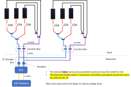
Technically, this is a 1S 6P arrangement with very distributed interconnects. If there is a short on the 10AWG wire, it would need to withstand all 82.2A.... and 10AWG will not be able to handle it.
However, if each set were on a separate SCC, it would be two separate PV systems and each one maxes out at 41.1A.
Thanks, but do you agree with my assessment that since the SCC is limited to 1500W of input power at a minimum input voltage of at least 22VDC, 68.2A is the maximum input current I need to assure my wires from DC breaker box / combiner to the SCC are rated for (meaning 6AWG wires and not 4AWG wires will suffice)?
FilterGuy
Solar Engineering Consultant - EG4 and Consumers
If I understand the question.... Then NO. Everything before the SCC must be rated for the full 82.2A.Thanks, but do you agree with my assessment that since the SCC is limited to 1500W of input power at a minimum input voltage of at least 22VDC, 68.2A is the maximum input current I need to assure my wires from DC breaker box / combiner to the SCC are rated for (meaning 6AWG wires and not 4AWG wires will suffice)?
The reason for this is that the PV circuit is designed to be able to handle a short without burning up and without an over-current device popping.
Let's imagine there is a short right at the SCC input. In this case, all of the current from all of the panels will be going through the short.
However, it *is * reasonable to use the limits of the SCC when sizing the output wires of the SCC.
This is precisely the sort of issue I was hopping you might help me discover before I committed to my plan.Hmmmmm. There may be a problem with this
View attachment 123706
Technically, this is a 1S 6P arrangement with very distributed interconnects. If there is a short on the 10AWG wire, it would need to withstand all 82.2A.... and 10AWG will not be able to handle it.
However, if each set were on a separate SCC, it would be two separate PV systems and each one maxes out at 41.1A.
Two separate SCCs is an option, so I have at least one solid solution which boils down to a matter of increased cost.
So the potential issue with my 2P x 3P design is not associated with a short within any of the panels, but rather a short between the + and - 10AWG wires on the roof, correct?
Is a short between PV wires really a realistic risk-case?
If there is a short on any of the 6 panels, the 15A fuses will protect against it causing any further harm.
If there is a short between 2 of the 10AWG wires, you could have up to 6 x Isc = 82.2A which would exceed the 55A ratings for 10AWG.
I agree but am just questioning the need to protect against shorts between those 10AWG wires. I could run them on opposite rack rails, for example, so they are nowhere near each other until they enter the roof-mounted junction box.
If you’re convinced this is a potential risk I should protect against, I take that input seriously and will adjust my plan accordingly.
2 parallel SCCs is one solution but wouldn’t another solution be possible by blocking reverse current?
For example, if I installed a 50A blocking diode between each 6AWG string and the 60A DC breaker, wouldn’t that protect against the very unlikely even if a shirt between 10AWG + and - wires?
Or something like this: https://www.amazon.com/gp/aw/d/B084...d2lkZ2V0TmFtZT1zcF9waG9uZV9kZXRhaWwp13NParams
Blocking diodes rated for over 42.2A will dissipate ~20W and will drop string voltage by ~0.5V but should protect against this risk you’ve pointed out, correct?
The fact that my 1500W @ 24V SCC only accepts a maximum of 6AWG on both input and output wires makes me suspect they have a different interpretation…If I understand the question.... Then NO. Everything before the SCC must be rated for the full 82.2A.
The reason for this is that the PV circuit is designed to be able to handle a short without burning up and without an over-current device popping.
Let's imagine there is a short right at the SCC input. In this case, all of the current from all of the panels will be going through the short.
However, it *is * reasonable to use the limits of the SCC when sizing the output wires of the SCC.
I’ll take my time to understand this issue before committing to purchasing my new SCC(s).
Their 40A SCC also accepts 6AWG, so two of those in parallel would be one solution.
Their 80A SCC accepts 4AWG but costs 3 times their 40A SCC, so your slowly steering me away from the idea of one SCC for the full 6P1S string towards getting a separate 40A SCC for each 3P1S string…
Their 30A SCC is ~15% cheaper but only accepts a maximum of 8AWG, so probably not worth considering (especially when considering that it’s always to use an SCC below maximum ratings).
FilterGuy
Solar Engineering Consultant - EG4 and Consumers
It is hard to say. I tend to worry about that kind of thing. Others don't.Is a short between PV wires really a realistic risk-case?
For example, if I installed a 50A blocking diode between each 6AWG string and the 60A DC breaker, wouldn’t that protect against the very unlikely even if a shirt between 10AWG + and - wires?
Blocking diodes rated for over 42.2A will dissipate ~20W and will drop string voltage by ~0.5V but should protect against this risk you’ve pointed out, correct?
Yes, that would certainly further reduce any risk of a problem. However, the NEC does not consider blocking diodes to be reliable enough to replace string fuses.
Also, since you are already tight on having the voltage to keep the SCC running, that .5V drop might be a deal buster.
If you’re convinced this is a potential risk I should protect against, I take that input seriously and will adjust my plan accordingly.
It would not meet NEC code, but maybe if you add the diodes and are extremely careful with the 10AWG routing it would reduce the risk to your comfort level. I can't really decide for you on this. All I can do is give you the engineering info and let you decide.
This reminds me of the line from the old Dirty Hairy movie, " How lucky are you feeling?"
Question: Instead of 2 x 1s3p, could you do 2S3P? The currents would all be the same as a single 1S3P but the voltage would double. Can the SCC handle that voltage? If you end up deciding you have to buy another SCC anyway maybe it would be a good idea to buy one that can handle the higher voltage.
FilterGuy
Solar Engineering Consultant - EG4 and Consumers
It is time for me to speak up about EPever. I am *really* not a fan of EPever. I had one that died. At first, I just thought I was just unlucky but then I started seeing other folks that have had problems with EPever. Some folks have seen problems where the unit would stop working till they totally disconnected it and reconnected it.... It would start working again for a while and then they would hit the problem again. It seemed like they were most likely to hit the problem when the controller was operating at max capacity.... and that is what you are planning to do.The fact that my 1500W @ 24V SCC only accepts a maximum of 6AWG on both input and output wires makes me suspect they have a different interpretation…
I’ll take my time to understand this issue before committing to purchasing my new SCC(s).
Their 40A SCC also accepts 6AWG, so two of those in parallel would be one solution.
Their 80A SCC accepts 4AWG but costs 3 times their 40A SCC, so your slowly steering me away from the idea of one SCC for the full 6P1S string towards getting a separate 40A SCC for each 3P1S string…
Their 30A SCC is ~15% cheaper but only accepts a maximum of 8AWG, so probably not worth considering (especially when considering that it’s always to use an SCC below maximum ratings).
I am always a little hesitant to badmouth people's equipment, but since the discussion has drifted into buying additional equipment I figure you need to know my thoughts on it.
Similar threads
- Replies
- 24
- Views
- 1K


