diy solar

diy solar

Wire size and fusing for 3P array

It is time for me to speak up about EPever. I am *really* not a fan of EPever. I had one that died. At first, I just thought I was just unlucky but then I started seeing other folks that have had problems with EPever. Some folks have seen problems where the unit would stop working till they totally disconnected it and reconnected it.... It would start working again for a while and then they would hit the problem again. It seemed like they were most likely to hit the problem when the controller was operating at max capacity.... and that is what you are planning to do.

I am always a little hesitant to badmouth people's equipment, but since the discussion has drifted into buying additional equipment I figure you need to know my thoughts on it.
I appreciate the head’s up.

I’ve been running a Tracer AN6420 for 18 months now (using this exact same circuit but with 3 380W panels) and have been happy enough with it’s performance that I’m thinking about doubling down.

I won’t say it’s been perfect - it’s finicky especially about getting changes to settings accepted, but I’ve learned to live with it’s quirks and other than that, it’s performed admirably (1.75MWh charged over 1 year).

My 6420AN has never charged at more than 40A, so 67% of max rating.

Based on your input, I think I’ll plan to maintain that 33% headroom on any future Epever purchases (so 40A minimum charger for each 3P1S string).
 
It is hard to say. I tend to worry about that kind of thing. Others don't.

Fair enough.
Yes, that would certainly further reduce any risk of a problem. However, the NEC does not consider blocking diodes to be reliable enough to replace string fuses.

Also, since you are already tight on having the voltage to keep the SCC running, that .5V drop might be a deal buster.
Yeah, between these two factors and the fact that as 80A model costs 150% the cost of 2 40A models, it’s starting to look like a better option to go with 2 40A SCCs…
It would not meet NEC code, but maybe if you add the diodes and are extremely careful with the 10AWG routing it would reduce the risk to your comfort level. I can't really decide for you on this. All I can do is give you the engineering info and let you decide.

This reminds me of the line from the old Dirty Hairy movie, " How lucky are you feeling?"
I’m probably feeling lucky enough to go that way, and if I only had space / room for a single SCC, I’d be ready to find a way to make that work.

But this exchange with you has been very helpful because it’s helped me to better-understand the safety benefit of two 3P1S circuits versus a single 6P1S circuit.

When I built the original ‘backbone’ in 2020, I planned space for a maximum of 3 SCCs. You’ve helped me to understand safety advantage of using that available space for 2 additional SCCs instead on one more powerful one…
Question: Instead of 2 x 1s3p, could you do 2S3P? The currents would all be the same as a single 1S3P but the voltage would double. Can the SCC handle that voltage? If you end up deciding you have to buy another SCC anyway maybe it would be a good idea to buy one that can handle the higher voltage.
Certainly, but there are 2 reasons I’d prefer to find a 1S solution if I can do so safely:

Shading: the roof I’m using suffers from severe and shifting morning shading. By going 1S, I’m never activating any bypass diodes (better for panel longevity) while maximizing the output from any panels that are shade-free. I’d lose a lot of output going 2S and because the shade is sharp and during the peak part of the day, I’d probably have replace bypass diodes more than I’d like to deal with.

Voltage: a 31VDC string is safer than a 62VDC string. It’s not a big deal and the higher voltage can be safely managed, but I’d probably consider the added risk of moving from 31VDC to 62VDCto be at l ast equal if not greater than the risk of a short between those 10AWG PV wires :).

At the moment, I’ve got inverters I’m happy with running off of my 24V battery, but there is far less selection in that category than there is fir battery inverters powered by 48V batteries.

So when I finally select my long-term hybrid inverter (2024? 2025?) these is a chance I’ll decide I need to switch from 24VDC to 48VDC.

If that ends up happening, my 2P8S LifFePO4 battery will need to be rewired as 1P16S and my two 3P1S strings will need to be reconfigured as two 1P3S strings or a single 1P2S string and a single 2P2S string.

The Epever SCCs I’m looking at are rated for 100V, so no issue handling 2S but if I really want to future-proof myself to keep all of my options open, I should probably pony up a bit more for the 150V models…

2P2S would translate to 980W of maximum charge power rating with a real-world peak charge power of 860W, so the 40A model would still have ~10% headroom on a real-world basis (and would just barely not clip on a maximum rating basis…

So a pair of 40A150V SCCs looks like the safest and most flexible configuration given my design.

Thanks again for being a sounding board.
 
At the moment, I’ve got inverters I’m happy with running off of my 24V battery, but there is far less selection in that category than there is fir battery inverters powered by 48V batteries.
The Epever SCCs I’m looking at are rated for 100V, so no issue handling 2S but if I really want to future-proof myself to keep all of my options open, I should probably pony up a bit more for the 150V models…
You can stay with the 24V system and you would not have to change the inverters to go to a 2S3P PV configuration. The SCC will convert the higher voltage to the lower voltage needed for a 24V battery.
Voltage: a 31VDC string is safer than a 62VDC string. It’s not a big deal and the higher voltage can be safely managed, but I’d probably consider the added risk of moving from 31VDC to 62VDCto be at l ast equal if not greater than the risk of a short between those 10AWG PV wires :).
Funny. I would be more worried about the 10AWG wires than the higher voltage..... Everybody has their own view of things.

Shading: the roof I’m using suffers from severe and shifting morning shading. By going 1S, I’m never activating any bypass diodes (better for panel longevity) while maximizing the output from any panels that are shade-free. I’d lose a lot of output going 2S and because the shade is sharp and during the peak part of the day, I’d probably have replace bypass diodes more than I’d like to deal with.
I would not personally be concerned about burning out the bypass diodes, but shading can definitely reduce output even with the diodes. Having 2 SCCs is certainly going to handle shading better than 1 SCC.
 
You can stay with the 24V system and you would not have to change the inverters to go to a 2S3P PV configuration. The SCC will convert the higher voltage to the lower voltage needed for a 24V battery.
Yes, I understand that.

1S (of my 245W panels) can only charge 24V (or 12V).

2S can charge 24V or 48V (or 12V or even 36V for sake of completeness).

3S can also charge 48V, 36V, 24V and 12V.


Funny. I would be more worried about the 10AWG wires than the higher voltage..... Everybody has their own view of things.
That’s exactly why I wrote that :).

Even the NEC has relaxed requirements for 24VDC systems versus 48VDC systems. Go to the extremes of 600VDC and the increased risk associated with higher DC voltages becomes clear.

I’m certain a 48V battery and 62V strings can be managed as safely as a 24V battery and 32V strings, but lower DC voltage is always safer if there is no good reason to go higher (primarily increased risk of arcing and greater hazard for any accidental shorting / mishap).

As you say, ‘chacun son gout’ ;).
I would not personally be concerned about burning out the bypass diodes, but shading can definitely reduce output even with the diodes.
Midday shading from a nearby tree translates to sharp shadows, meaning any shade-free panel thirds will push peak Imp through bypass diodes associated with any shaded third-panels.

The fact that pretty much all panel manufacturers void their warranty if panels are exposed to any shading tells me all I need to know.

I’m more comfortable knowing my 1S 24V-battery voltage limits means I will never be activating any bypass diodes (again, ‘chacun son gout).

Not a safety issue but rather a potential hassle issue.
Having 2 SCCs is certainly going to handle shading better than 1 SCC.
If the panels of the two strings are poorly-matched or have different orientations, certainly.

With 6 well-matched panels on identical roof surface, 2 MPPTs versus one MPPT won’t make much of any difference in the presence of sharp shade.

The shade-free panels will operate at full Vmp and any panels with sharp shade will either be completely blocked or will operate at partial Imp (if the sharp shade only partially blocks the most-blocked third-panel).

Since shading primarily reduces current output at the same voltage of Vmp when blocking diodes cannot be activated, there is not much of a gain to be had by having two versus one MPPTs (though I will go to the trouble of putting my 3 strongest / least-degraded panels on one string and the weakest 3 on the other string ;)).
 
Last edited:
OK. That does not change the current calculation.

View attachment 123659


What are the Voc and Vmp of the panels?

Most charge controllers need 4 or 5 volts above battery voltage just to turn on. That means the panel Vmp should probably be at least 36V for a LiFePO4 battery (Preferably a few volts higher). You might get away with Voc of 36V, but that would be pushing it, Particularly on hot days.
I’m revisiting this one last time before purchasing components and would appreciate your confirmation I’ve got everything corect.

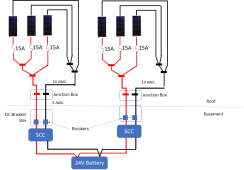
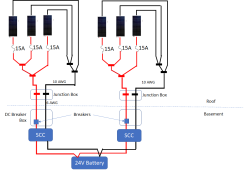
I’m going with 2 separate SCCs for reasons we discussed earlier and only one of those 3P strings will need to be combined onto a single 10AWG wire before entering my junction box (so the exact circuit you picture above).

The 15A MC4 fuses are rated to 75C and will connected directly to Staubli MC4 Y connectors rated for 50A up to 85C.

The first Staubli MC4 connector output will connect to a Windy Nation 8AWG MC4 extension cable rated for 55A up to 90C which will connect to one input of the second Staubli MC4 Y connector which will connect its second input to the third panel through another 14A fuse.

The output of the second Staubli Y-connector will connect to a short 10AWG PV wire through a Staubli MC4 connector and will go on enter the roof-mounted junction box where it will be connected to the 6AWG home run wires carrying the DC current from roof to basement.

I used the 8AWG extension cord to reduce voltage drop and I used the short 10AWG PV wire into the roof-mounted junction box because that box only has cable glands for 10AWG.

So the 10AWG MC4 connector on that short 10AWG wire seems like the most critical component on the entire circuit.

The Staubli PV-KBT4/6X-UR has a UL rating for 50A @ 85C with 10AWG wire: https://www.staubli.com/content/dam/spot/SOL-Main-11014092-en.pdf#page=18

So I am pretty sure that by assuring that I get that specific Staubli MC4 connector I will be able to enter my roof-mounted junction box with 10AWG PV wire and have a circuit rated for 50A (from the MC4 connector) up to 75C (from the fuses), exceeding my requirement of a rating of at least 41.2A (156.25% x 3 x Iscwc of 8.782).

Anything I am missing or have I understood all of this correctly?
 
OK...

1671681347421.png

FWIW: The NEC requires the PV disconnect to break both sides of the circuit.
 
The last Y connector connecting into the final 10AWG entering the roof-mounted junction box clearly need to be rated for more than the 41.2A worst-case 3x Iscwc x 125% x 125% rating, but since only that final Y connector and the final MC4 connector may ever see the full 3P Isc current in the case of a short further down, can’t I get by with vanilla 30A MC4 connectors upstream of that?

Hmmm, You are probably correct that the upstream Y will never see the full 41.2A.
 
Hmmm, You are probably correct that the upstream Y will never see the full 41.2A.
That’s what I thought - the upstream Y as well as the MC4 connector on the wire connected to the upstream Y can only see a maximum of 2/3 of the 41.2A (meaning a 30A rating for those two connectors should be fine…).
 
Hmmm. How important do you think that is with an SCC? The directions only talk about a breaker / disconnect on the + wire…
Since neither the positive or negative are tied to ground, the negative circuit could be hot in reference to ground even when the positive is disconnected. In your case the voltage is low enough that it is probably not an issue......technically still a code violation. I would worry a lot more if the string was at 200V.
 
Since neither the positive or negative are tied to ground, the negative circuit could be hot in reference to ground even when the positive is disconnected. In your case the voltage is low enough that it is probably not an issue......technically still a code violation. I would worry a lot more if the string was at 200V.
My SCCs are common-negative and I thought that meant that the ground terminal of the battery connected to the SCC’s negative output terminal was internally shorted to the negative PV input.

Doesn’t that mean that the PV negative is at least connected to battery negative and there is little/no reason to disconnect PV negative when PV positive has been disconnected / breaker has tripped?
 
Doesn’t that mean that the PV negative is at least connected to battery negative and there is little/no reason to disconnect PV negative when PV positive has been disconnected / breaker has tripped?
If the battery negative is grounded and the SCC has a common Negative, yes. However, I don't think the NEC has a carve-out for this. (I wonder why?)
 
If the battery negative is grounded and the SCC has a common Negative, yes. However, I don't think the NEC has a carve-out for this. (I wonder why?)
I don’t believe I have my battery negative tied to ground, but both the SCC and the GTIL inverters it is connected to are grounded. Won’t that effectively ground the battery negative?

Is it generally recommended to ground battery negative?
 
If the battery negative is grounded and the SCC has a common Negative, yes. However, I don't think the NEC has a carve-out for this. (I wonder why?)
This entire exchange with you has been enormously helpful to me and I want to thank you for your engagement and insight once again.

If the Forum has an award for ‘Member of the Year’, you’d get my vote :).

I’m pretty much all set on my plan for adding 2 3P1S strings but still have some confusion in two areas I was hoping you might be able to enlighten me:

Temperature Ratings: I’m pretty sure that as long as all my roof-mounted circuit components are rated to take over my maximum current rating at over my maximum ambient temperature, I’m good to go, but the rules about derating to the temperature rating of the lowest-temperature-rated component have me a bit confused so I’d appreciate a confirmation. Here is a rundown:

Highest recorded temperature where I live is 107F / 41.7C.

15A MC4 fuse holders and fuses are rated to 125C

I can’t find a temperature rating for the 15A fuse itself but that should not be a concern since being too hot exults in the fuse blowing (not a safety concern).

Vanilla MC4 connectors rated for 30A up to 90C.

10AWG USE-2 wire freestanding in air rated for 55A up to 90C.

The first generic MC4 Y connectors for is rated for 30A up to 90C.

The second Staubli MC4 Y connector is rated for 50A up to @ 85C.

The high-current Staubli 10AWG MC4 connector is only rated for 31A up to 90C but is also rated for 50A up to 85C (UL).

So I am pretty sure that this circuit provides me with a rating of 50A up to 85C (as well as 30A up to 85C on the 2P and 1P branches), we’ll beyond the requirement of 41.2A to temperatures of at least 41.7C.

Is that the correct understanding and the appropriate way to summarize?

Wiring Losses: I’ve seen all the recommendation to size wiring to stay under voltage drops of 3% or at least 5% but as I look at the cost of 8AWG versus 10AWG PV wire, I’m coming to the conclusion that this is merely a question of lost efficiency (within the roof-mounted PV wiring) and not worth it in terms of ROI.

If I use 3 parallel runs of 8AWG wire to reduce wiring losses, I can get combined wiring losses (including the 6AWG home run wires from roof to basement) down to 3.72%.

If I use a single run of 10AWG wire from 3P combination point of 3 panels into the roof-mounted junction box, rooftop wiring losses are 2.57% higher for combined wiring losses of 6.29%, but t the the wiring cost by more than 50%.

The loss of an additional 2.57% of potential annual power generation translates to ~26kWh of list export annually, or $1.40 at wholesale compensation rates.

Spending another ~$70 to capture an additional $1.40’s-worth of energy per year translates to a 50-year break-even (waaaay to long for my tastes).

So I’m convincing myself to stick to the simpler / cheaper 10AWG wiring unless you tell me there is more to it than that and losing another 2.57% to wiring losses on the roof introduces an additional safety hazard.

To summarize, with 10AWG USE-2 wiring on the roof I will lose 3.38% in I2R losses between panels and roof-mounted junction box and then another 2.71% in I2R loses through the 6AWG home run wires running between roof and basement - do you see any problem with that (other than lost efficiency)?
 
The rules about derating to the temperature rating of the lowest-temperature-rated component have me a bit confused
That is because they are extremely confusing. It is a complex multi-step process to do all the derating, and I have to go look it up every time I try to do it.

Here are the things that the full derating and adjustments take into account: (At least the ones I remember off the top of my head)
  • The current used for calculating everything is 1.56 x Isc.

  • If the wire is in a conduit that has more than 2 current-carrying conductors, there is a derating formula. This is because of the heat buildup of the multiple conductors. (Note that a ground wire is not considered a current-carrying conductor)

  • If the conduit (conductor?) is run within certain distances of the roof, there are additional derating requirements. This is because the temperature right on a roof is higher than above the roof.

  • As you mentioned, the device with the lowest temp rating drives the temperature column in the wire Ampacity chart that must be used.
    (If a breaker has a 75degree rating and the wire has a 90degree rating, the wire ampacity must be determined from the 75deg column in the ampacity chart. This is to prevent the wire from getting too hot for the breaker)
As far as I know, none of the deratings depend on ambient temperature.

There is a certain sequence to apply all the factors, but as I said, I have to look it up each time.
I don't have time right now but I will try to find instructions for how to do it. (Maybe this would be a good resource)

Wiring Losses: I’ve seen all the recommendation to size wiring to stay under voltage drops of 3% or at least 5% but as I look at the cost of 8AWG versus 10AWG PV wire, I’m coming to the conclusion that this is merely a question of lost efficiency (within the roof-mounted PV wiring) and not worth it in terms of ROI.
The wiring size requirements in the NEC are all about safety and not about efficiency or even functionality. Increasing wire size to reduce voltage drop is an engineering decision that the NEC does not address. The reasons to increase the wire size could be driven by 2 things:

Functionality: If the voltage drop is so great that the device the wires are going to won't work properly, there is a need to increase the wire size.

Efficiency: The voltage drop represents energy loss. If the loss is acceptable for the application, then it is not a reason to increase the wire size.
In the early days of solar, Panels were extremely expensive so people put in as few as possible and tried to get everything they could out of the limited resource. Today, maybe just having more panels and living with a higher line loss is the more economical way to go. That is an engineering calculation that must be done on a case-by-case basis. (The tendency of us DIYers is to put in more panels *and* try and milk everything we can out of them :))
 
The safety issue from derating / determining max circuit ampacity are basically around handling worst case scenarios at a single point (or segment) in the circuit. Be it a part of the conduit that has unusually bad heat dissipation or terminals.

The local conditions on a conductor don't care about how long the wire is (*), only how much current is going through that wire and how much local conditions around insulation/ambient temperature/whatever are causing complications for it.

Voltage drop is unlikely to affect MPPT since they already have a wide operating range.

(*) There is an exception for adjusting derate based on the wire (a good heat conductor by definition) dissipating heat out from a problem spot across the rest of the circuit, if the problem spot is below X% of the length of the circuit, I can't remember the code section. But that is different from voltage drop. I am not sure if it is applicable to PV vs just for regular AC.
 
The wiring size requirements in the NEC are all about safety and not about efficiency or even functionality. Increasing wire size to reduce voltage drop is an engineering decision that the NEC does not address. The reasons to increase the wire size could be driven by 2 things:

Functionality: If the voltage drop is so great that the device the wires are going to won't work properly, there is a need to increase the wire size.

Efficiency: The voltage drop represents energy loss. If the loss is acceptable for the application, then it is not a reason to increase the wire size.
In the early days of solar, Panels were extremely expensive so people put in as few as possible and tried to get everything they could out of the limited resource. Today, maybe just having more panels and living with a higher line loss is the more economical way to go. That is an engineering calculation that must be done on a case-by-case basis. (The tendency of us DIYers is to put in more panels *and* try and milk everything we can out of them :))
This is pretty much how I understood it but I appreciate the confirmation that there is not some aspect I’ve overlooked.

I consider the issue of wire sizing now closed and will follow up on temperature ratings in a separate post…
 
That is because they are extremely confusing. It is a complex multi-step process to do all the derating, and I have to go look it up every time I try to do it.
Good to know I’m not the only one :).
Here are the things that the full derating and adjustments take into account: (At least the ones I remember off the top of my head)
  • The current used for calculating everything is 1.56 x Isc.
Yes, understood.
  • If the wire is in a conduit that has more than 2 current-carrying conductors, there is a derating formula. This is because of the heat buildup of the multiple conductors. (Note that a ground wire is not considered a current-carrying conductor)
Pretty sure it is more than 3 (not including ground), not 2 (I’m using two 3-conductor + ground metal clad conduit for my 3 6 AWG home runs for precisely that reason).
  • If the conduit (conductor?) is run within certain distances of the roof, there are additional derating requirements. This is because the temperature right on a roof is higher than above the roof.
Yes, understood that as well. I’ll be affixing all conductors at rail height to avoid any derating for that.
  • As you mentioned, the device with the lowest temp rating drives the temperature column in the wire Ampacity chart that must be used.
This is the area I’m still confused about.
  • (If a breaker has a 75degree rating and the wire has a 90degree rating, the wire ampacity must be determined from the 75deg column in the ampacity chart. This is to prevent the wire from getting too hot for the breaker)
I cannot find whatever reference made me believe my 15A fuses were only rated for 75C but I’m still not understanding why using a fuse only rated for 75C would require 10AWG USE-2 wire would need to be rated for 40A rather that 50A (85) of 55A (90C).

I suppose the argument is that the wire heating up to it’s maximum temperature can cause the fuse to exceed it’s maximum rated temperature.

At least as far as understanding the logic, this helps, so thank you.

In my case with a 15A MC4 fuse, I can’t believe there is any safety issue since if the fuse temperature exceeds it’s maximum rating, the result will be to blow the fuse (so avoiding nuisance trips at most).

In addition, I can’t believe an MC4 fuse would be successful if it caused USE-2 PV wire to be derated all the way back to the 75C column.

I probably misread the fuse spec and will look more carefully into that, but in any case, this interpretation would mean that I have to use the 85C column for 10AWG USE-2 because the Staubli MC4 connectors are only rated for 50A up to 85C, not 90C.

There is no 85C column for 10AWG wire in Table VI but the 80C column rates 10AWG for 50A, so 10AWG at 85C must be able to handle at least 50A.

It’s only the urea themselves that would need to be derated, correct? All of the components connected to those wires rated to handle over 50A at temperatures up to 85 or 90C will be fine as long as the wires are not heating up past 80C, correct?
As far as I know, none of the deratings depend on ambient temperature.
At least for conductors running through enclosed spaces, I believe a derating based on maximum ambient temperature of the enclosed space must be applied: https://www.productinfo.schneider-e...map/$/CorrectionAndAdjustmentFactors-F20BC8E5

The 6AWG home run wires I have running through my attic are rated for 90C but the attic can reach temps as high as 140F / 60C and so I have derated the maximum ampacity of those conductors to by 29%.

For freestanding USE-2 wires in air, I guess no derating is required? (As long as you are far enough above the roof surface).
There is a certain sequence to apply all the factors, but as I said, I have to look it up each time.
I don't have time right now but I will try to find instructions for how to do it. (Maybe this would be a good resource)
I believe this would be a great resource! (whether in this thread or somewhere else).
 
Back
Top