diy solar

diy solar

Wire type and size-need to get this right

You have it set to 120 and I have it set to 240 but it's sort of doing my head in right now to justify why or if we get to use the 240v calculation for feeder voltage drop even though they can carry 120v currents at full amperage. Maybe we just don't typically expect that much of an imbalance so we tolerate higher potential voltage drop in that scenario.

Wait for @timselectric or another expert to clarify here.
Good callout. I was basing my figures above on 240 assuming the inverters were going to be split phasing. If the run is 120, lower voltage = more amps. The calculations would need to be for 86 amps for 120

edit: also one less wire at 120
 
Good callout. I was basing my figures above on 240 assuming the inverters were going to be split phasing. If the run is 120, lower voltage = more amps. The calculations would need to be for 86 amps for 120

edit: also one less wire at 120
Yeah I'm used to sizing feeders for 240 and never really considered calculating the 120v voltage drop even though it is relevant if you had a completely unbalanced full amperage load. Reaching the edge of my knowledge here.
 
True, but a 200A panel is easier to buy, cheaper in many cases, and has room for individual circuits. But that 200A breaker means ya gotta feed it with 200A calculated wire… (no way 4/0 aluminum can handle 200A for long!)
Sure, 125A panels are available and cheap often, but limit the number of circuits you can run.
A 200a panel doesn’t have to be feed by the main 200a breaker no?

Back feed 50a breaker?
 
I’m past my knowledge here as well.

I thought with two Quattros I would run two lines (L1 and L2) at 120 volts each. Plus a neutral and a ground for 4 wires total.

I don’t think I understand how two Quattros and split phase works. In the short term, I was going to use one Quattro and see how it goes.

@sunshine_eggo Would you mind shedding some light? I’ve looked at the Victron info and the Victron forum but am still unclear.

I have two Quattros working in split phase. Q1 provides L1-N-G connections and Q2 provies L2-N-G connections. N and G are common between them. The N-G bond is provided ONLY in the L1 inverter.

With one quattro, you are limited to 120V, L-N-G.

Anything unclear?
 
That is perfectly clear.

When calculating line size, I need 4 conductors.

And I need to size L1 and L2 each using 120 volts and 42 amps.

And I will size the neutral and ground to match the L1 and L2.

Is this correct?

Many thanks.
 
Here is another debate of the question at hand here:


Basically, it is common practice to size feeders for 240v voltage drop, and yes if you run a totally unbalanced load you will get twice the voltage drop.

So if you were running 120v loads and you really want only 3% voltage drop you would input 120v in the calculator. But normally, a subpanel is sized for 3% at 240 and the greater voltage drop in the case of 120v unbalanced full current loads is tolerated.
 
@sunshine_eggo Does Victron provide easy access to a voltage output adjustment?

If you have 120v a 6% drop won't hurt anything. But if they're locked at a franken-Euro 115/230 then voltage drop is a bit more crucial.
 
That is perfectly clear.

When calculating line size, I need 4 conductors.

And I need to size L1 and L2 each using 120 volts and 42 amps.

And I will size the neutral and ground to match the L1 and L2.

Is this correct?

Yes, but output may need to be oversized due to passthrough and powerassist.

N will never carry more than L1 or L2. If current is used on both legs, N is actually reduced to the difference between the two.

Manual specified gages consider the transfer switch rating + powerassist. If you are setup to provide less at the input, you can size accordingly at the output.

I'm inputting only 13A via generator, so 55A max output - using 6awg.
 
Thanks for the link.

I guess I don’t know how to balance the load given the 240 volt will the the intermittent mini split. I can split the circuits with best guesses between L1 and L2 but it will be rough justice.
 
That is perfectly clear.

When calculating line size, I need 4 conductors.

And I need to size L1 and L2 each using 120 volts and 42 amps.

And I will size the neutral and ground to match the L1 and L2.

Is this correct?

Many thanks.
Keep in mind as mentioned above, you can get the wire bundled. Using HD as example, local electrical supply would likely be cheaper.
https://www.homedepot.com/p/Southwire-500-ft-2-3-Black-Stranded-CU-W-G-Tray-Cable-44342401/202316565 (They also sell by foot)
 
Yes, but output may need to be oversized due to passthrough and powerassist.

N will never carry more than L1 or L2. If current is used on both legs, N is actually reduced to the difference between the two.

Manual specified gages consider the transfer switch rating + powerassist. If you are setup to provide less at the input, you can size accordingly at the output.
Sorry, I don’t know how to operationalize some of this.

Are you saying I need to upsize the conductors account for pass through and power assist?

I read the N line as saying N will never need to be larger than L1 or L2. Great.
 
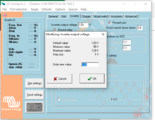
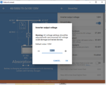
I do see that voltage at the inverter can be adjusted up to 130 volts.

Doesn’t this change my calculations pretty significantly? If I set at 130, there is no downside. Right?

Edit-I see that 130 doesn’t help as much as I thought it might.

IMG_0460.jpeg
 
Sorry, I don’t know how to operationalize some of this.

Are you saying I need to upsize the conductors account for pass through and power assist?

Yes.

From the manual:

AC-out-1 (see appendix A, maximum torque: 7 Nm)The AC output cable can be connected directly to the terminal block "AC-out". With its PowerAssist feature the Quattro can add up to 5kVA (that is 5.000 / 120 = 42A) to the output during periods of peak power requirement. Together with a maximum input current of 100A this means that the output can supply up to 100 + 42 = 142A. An earth leakage circuit breaker and a fuse or circuit breaker rated to support the expected load must be included in series with the output, and cable cross-section must be sized accordingly. The maximum rating of the fuse or circuit breaker is 142A.

So, take whatever you're going to feed the input and add 42A to it.
 
I do see that voltage at the inverter can be adjusted up to 130 volts.

Doesn’t this change my calculations pretty significantly? If I set at 130, there is no downside. Right?

Edit-I see that 130 doesn’t help as much as I thought it might.

128V is the actual limit in the software.

If 128V is what it takes to show 120V at the end of your wires, no problem. You will still be current limited to the VA, i.e., 5000/128 = 39A.

Most equipment is happiest at the rated 120V.
 
Back
Top