diy solar

diy solar

New Daly "Smart" BMS w/ Communication. (80-250A)

Hello all,

Not really Solar related but mainly on the Daly BMS as i found the most info here.
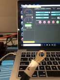
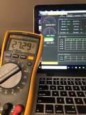
I have the Daly 30/60A Smart BMS with the Bluetooth adapter and use the newer app "Smart BMS" from Daly.

Now i want to change some parameters but it requests an 6 number password.
I searched like crazy but found nothing.

1598798238091.png1598798259668.png1598798282194.png

I hope anyone here has an idea since the response from Daly is crazy slow :)

Thanks!
 
Ok update .... the type of BMS i have is a dumb one. It can send its info but is not possible to configure anything.

Great work Daly with providing false info ....
 
I was starting to consider one of these high current Daly BMSs for my cells that will be used for my home solar array to work with a SolArk inverter.
I found this thread while looking for information about the CAN bus to see if it might be able to send status information to the SolArk. Thankfully, the SolArk is battery agnostic. It doesn't require a battery, and does not require communication with the battery to use its storage capacity.
The discussion on here does not inspire a lot of confidence in these products.
What other 200A+ BMSs are out there for this kind of application? I find a couple on AliExpress. Wondering who had experience with other brands.
 
My only experience is with Orion and recently with Overkill (JBD) on a 12 volt pack.
Both Orion and Skybox have CANBUS but it is not plug and play. Orion has lots of bells and whistles for EVs and many contact closure signals it can send. As far as I an tell the only contact closure on the Skybox is the RSD switch. I have already inquired about the generator start functions and whether they can be configured, but no luck there. Using RSD to shut down both inverter and AC coupled GT inverter is drastic when all I would need is a simple stop charging command.
The thing that keeps recurring is the thought of an Arduino with a CANBUS interface. If I could get the library of commands from Outback I might know where to start. The most important one that I need is a stop charging command. I have no Arduino skills.
 
Last edited:
I have no Arduino skills.
There aren't a lot of skills needed.
Download the app to your computer and ryn it. Open the example sketches and watch videos about how things work. Once you get comfortable with it, go search for sketches where people have already done what you are trying to do. Usually there is something close and you can just tweak it.
SolArk is a 48V system, so I need to run 16S.
Excited about 14kWh of battery! Just need a good BMS. Someone on here was praising a JK BMS. 2A Active balance sounded promising.
 
After a bunch of research and digging around, I settled on the Heltec 200A BMS. It has 2A Active balancing capacity and CAN bus.
Will it be compatible with the SolArk protocol? Who knows?! I learned that the SolArk doesn't require communication with the batteries, for it to display better, data, I could resolve any incompatibility later.
 
Hi! I'm using the sinowealth software with a Daly 4S 80A LiFePO4 battery. I'm curious, the help file is all in Chinese, does anyone happen to have a translated version? I've uploaded what's included here.
I have spend some time using Google translate + word editing for readable translation
 

Attachments

  • Sinowealth BMS Tool Introduction V0.1 English.pdf
    1.1 MB · Views: 51
OK so I bought the 250a version of the Daly Smart BMS.
I noticed when I'm charging 10.4 a from my PSU the BMS PC software indicates 11+ amps.
Do I need to do the "10 amp calibration" from the "Engineering" menu?
I had assumed this was something they would have done in the factory.
Sorry for the repost, I wrote this in another Daly thread and nobody responded.
How have you determined that the current is actually 10 amps?
 
OK so I bought the 250a version of the Daly Smart BMS.
I noticed when I'm charging 10.4 a from my PSU the BMS PC software indicates 11+ amps.
Do I need to do the "10 amp calibration" from the "Engineering" menu?
I had assumed this was something they would have done in the factory.
Sorry for the repost, I wrote this in another Daly thread and nobody responded.
I had that bms and after a clean start it began to generate demonstrably false current and voltage readings. The bms reacted as if the false readings were true, and eventually did not come back on after a reset procedure.

As an example I’ve attached a picture showing a non zero current with the load side wire detached. If you get stuck Daly had suggestions which i could retrieve from AliX. They are different from what appears in the documentation. I can’t comment on their effectiveness since I couldn’t execute them on a bricked device.
 

Attachments

  • A7CDDD13-B5F3-4015-AEED-2FCA5EEAE5BD.jpeg
    A7CDDD13-B5F3-4015-AEED-2FCA5EEAE5BD.jpeg
    108.9 KB · Views: 50
Last edited:
How have you determined that the current is actually 10 amps?
Good question,
I have a decent battery Ammeter I connected to verify. It does show slightly higher current coming in to the battery from the BMS.
To be clear, I have 2xPSUs (identical PSUs) in series pushing out the voltage I need.
The voltage displayed on the PSUs (each set with identical voltage) the last time I checked was 10.43a. The BMS software indicated 11.4a and the ammeter connected to the battery shows 10.7a.
I should mention my PSUs I got from Alibaba. They are max 32v 10a units. They are also Chinese (like the BMS) as surely is the ammeter though it wasn't a cheapo cheapo one. Cost me about $35 for the ammeter.
 
I had that bms and after a clean start it began to generate demonstrably false current and voltage readings. The bms reacted as if the false readings were true, and eventually did not come back on after a reset procedure.

As an example I’ve attached a picture showing a non zero current with the load side wire detached. If you get stuck Daly had suggestions which i could retrieve from AliX. They are different from what appears in the documentation. I can’t comment on their effectiveness since I couldn’t execute them on a bricked device.
Yikes.
So far the cell readings were fine. The other day I switched the cells back to all parallel mode to top balance again (to 3.65) as I had hoped the BMS would help out enough before (matching new cells). To my chagrin, the BMS would not turn on in a low voltage setting like this.
I also have the ANT BMS and it was able to still protect cells even when they were all in parallel running at just 3.2v.
 
One other thing, I don't think this matters but the way the cells are arranged,
2 parallel collumns, the leads for the BMS were not long enough so I cannibolized leads from a failed ANT BMS (bad mosfet I think).
I made sure the leads were all equal lengths so no weird resistance differences. I soldered nicely and shrinktubed the connections.
Can the additional resistance from the extended wire lengths really be causing such a massive misreading on the amperage?
just wondering if they have something hardcoded in their software.
 
Can the additional resistance from the extended wire lengths really be causing such a massive misreading on the amperage?
just wondering if they have something hardcoded in their software.
For sure the amperage is not readed from this wires. I have never opened a Daly BMS, but amperage is evaluated either with hall effect or with a shunt.
Given the about 10% deviation you see, I would fgive a try with the calibration.
If this possibility exists, there must be a reason ;-).
 
For sure the amperage is not readed from this wires. I have never opened a Daly BMS, but amperage is evaluated either with hall effect or with a shunt.
Given the about 10% deviation you see, I would fgive a try with the calibration.
If this possibility exists, there must be a reason ;-).
Yes of course, I meant voltage variations on cells. I think I read another person's post about the Daly smart BMS being wrong on cell voltages and in my tired stupor applied this conversation... thanks for checking me. definitely a duh moment.
 
@Jeremiah, from your statements, it sounds like you are using a clamp-on style amp meter to measure your current. I recommend that you use a shunt instead. It is a much more accurate method of measuring high current.
It seems that you don't know which value to trust, and it is understandable. You should have a dependable, accurate meter like a Fluke and have it calibrated by a traceable lab before you decide which Chinese product to believe. I know it is money out, but if you are 10% out at 10A, things can get dangerous at 100A.
 
One other thing, I don't think this matters but the way the cells are arranged,
2 parallel collumns, the leads for the BMS were not long enough so I cannibolized leads from a failed ANT BMS (bad mosfet I think).
I made sure the leads were all equal lengths so no weird resistance differences. I soldered nicely and shrinktubed the connections.
Can the additional resistance from the extended wire lengths really be causing such a massive misreading on the amperage?
just wondering if they have something hardcoded in their software.
I think you are smart to be careful about lead resistance. I had a couple of crimped leads which tested closed but opened up when I attached them to the terminals. I spent a lot of time chasing that down. To confuse things further the bms failure looked like one of the cell sensing circuits developed a problem, which eventually drove it into perma-off. Note cell 1 reading in picture - DMM measured 3.35x.
 

Attachments

  • 61028074-2626-41F2-9467-2A9D8A735902.jpeg
    61028074-2626-41F2-9467-2A9D8A735902.jpeg
    131.2 KB · Views: 27
claiming the current rating for charge is 250A. (I would still de-rate by 40-50%)
This arena of questions is part of why I chose the Chargery BMS with a 300 amp shunt for my first DIY LiFePO4 build (and noticed you can go up to a 600 amp shunt). I liked learning (there is more of a learning curve w the Chargery) from having to study all the configuration adjustment options (first by studying manual, and then opinions about the options, and then by doing it yourself). Of course one added challenge to the Chargery BMS is adding your relay cut offs. I figured out some options I liked combining some Solid State Relays with some Kilovac EV200 500 amp rated relays that have a very low 1.7 watt rating for coil clamping relay switch (with their built in coil economizer) after a brief inrush current that closes the mechanic relay switch. I liked finding some of those Kilovacs used at low price on eBay (overkill for my need w up to 500 amp rating/ at good DIY price. My specific needs for relays might be different that many as I am dialing my a 3 unit All In Ones / MPP LV2424 set up. ... just thought to leave my comment as food for consideration. :+)
 
Back
Top