diy solar

diy solar

Batrium Watchmon Install

A couple of little things…
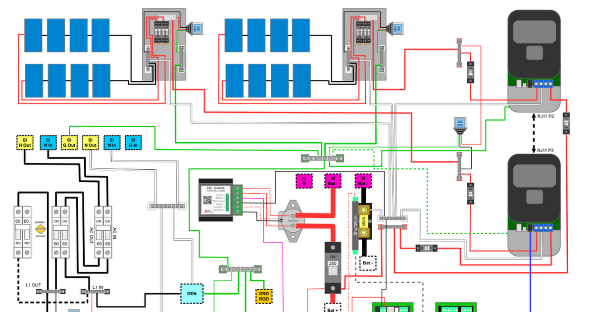
From the batteries - you have a class T fuse (great!), then the battery disconnect (great), then it looks like (if I am reading it correctly) it goes to your contactor (which is powered through a Pre-Charge - Great), but then there is a 250a breaker (Why? - if the breaker is off - you just wasted the pre-charge voltage ramp-up). If you just want a switch use the contactor (through the Batrium software).

Also, does your solar charge controllers have a wire/relay, etc so that the Batrium can control the charging- charge OK vs Not OK.

Also, you have three 300VDC (lighting arrestors?). I can see the purpose of each at the combinator panel, but then you have only one more after that - I would have thought you need zero or two or both panels going through it. ( I really don’t know enough here to comment- other than it seems off to me.

Have you already purchased the Batrium? You may want to look at the K9?

God luck
 
Interesting. My initial config (16S) and conversations with Batrium steered me to the block mon. An MM5 +1 MM8 is about $230 cheaper than MM4+28 blockmon.

I'm not too concerned about .3A balancing vs. 1.2A isn't a big concern. All cells have been tested for capacity and interleaved within a module to ensure each 21P cell capacity is extremely close. I'll have 4A active balancers on there and plan to disable Batrium balancing in most cases.

I may actually like not having the balance heat at the cells.

Thanks for that.

I have all the components including the land... just not the time! :(
Why didn’t you go with the Watchmon Core and & K9s?
 
Thank you both for your input.

Why didn’t you go with the Watchmon Core and & K9s?
Have you already purchased the Batrium? You may want to look at the K9?
Pictured, although redrawn by hand as a rough representation, is the WatchMoCore + CellMate-K9 bundle ? https://www.batrium.com/collections/kits/products/watchmon-core-k9

but then there is a 250a breaker (Why?
Because it is built into the prewired SMA Midnite Panel? It wont be hard to ensure it is turned on before sending current down the normal connection terminal. I eventually plan on making multiple battery modules like the one seen in the diagram, each 16s with its own k9 as pictured.
Should I move the contactor north of the breaker? to make better use of the precharge function?

Also, you have three 300VDC (lighting arrestors?).
One is VAC at Line 1 IN / OUT
One is VDC used for the Classic charge controllers input
Both of these are found on the main panel under the SMA. This is the standard configuration for this box. When I add another Classic charge controller I will have to add another VDC arrester as well (something I am thinking about as I have enough panels on my pallet to operate three charge controllers)

There is one extra on each combiner box which are VDC as well. I actually ended up getting a midnite 12 panel box and installing two arrestors on it, one for each "leg" going back to the charge controllers.

Updated drawing to be more clear and moved relay down range of the breaker. EDIT: Upating url to v5 which is cleaner https://drive.google.com/file/d/1zBiWcO6m7j04EqA0LuignK4pw0Ez3b8m/view?usp=sharing
 
Last edited:
Sorry for the attention there LithiumSolar, wanted to post here given you are the only place I could find in the forums with a documented build out and I wanted to contribute and seek out guidance inside the same thread vs starting another thread ;)
 
I see two different options:
First the way I did it. The Batrium, shunt, pre-charge, and signal relay to pre-charge/contactor are all wired “before” the contactor. This allows the bms to start and restart.

The second way is those four items are powered after the contactor. That way if the battery goes Critical everything shuts down and YOU have to manually restart it. (You will need to figure out the manual restart procedures.)
In my trailer I power the Watchmon in 2 different ways....

1) Powered from the battery - the circuit has a breaker (on/off switch). This is normal mode when the MPP Solar 3048LV and battery is active.

2) Powered via the USB from the trailer computer. When in storage, I use a bypass to skip the MPP Solar and feed 120v directly to the distribution panel. This let's me shut off the inverter and disconnect the battery but yet use the trailer computer's USB to power the Watchmon (without draining the batteries) so I can monitor the cells and the temp either on the trailer computer or via wifi of the Watchmon.
1651101675674.png

My point is the USB option can be useful as an alternate power source to monitor without the battery being 'enabled'.
 

Updated the drawing to be a little cleaner in my previous post. Is there any downside to having the watchmon take power from B+ while the PreCharge is down stream of the main breaker if the breaker is off? Just thinking "what ifs" ... from what I can tell the watchmon > precharge is just a input sensor vs providing power which is likely from the B+ source down stream on the breaker in the way I have it configured now.
 
Also, does your solar charge controllers have a wire/relay, etc so that the Batrium can control the charging- charge OK vs Not OK
Just now remembering to respond to this.

The batrium will only control the contactor which would cut off charging to the battery ... BUT that was with version 3 of the diagram before you mentioned the 250v breaker being useless in how I had it configured.

The solar charge controllers themselves have their own shunt to monitor the batteries ... my RSP2000's I don't think have an input either ... they are just CC CV ...

Looks like I might have to reconsider my diagram again to bring back the usefulness of the contactor. Or revert to the previous version and change startup procedures for the inverter.
 
I just figured I would give an update on my lithium battery- it has been working great! Boring - huh ?.

In other news…
When I was a the Quartsite RV show last January- I picked up a Victron Dc-Dc charger (non-isolated). It sat around for a while - but I finally got it (mostly) installed. I want to add a relay so it will not run except when the ignition is on. My rig has a dc charger to charge the chassis batteries when the generator/shore/solar is charging the chassis batteries. I need to add the relay because I end up in a charging loop (that Just wastes power).

I added the Dc-Dc charger because I wanted to make sure that on a driving day we arrived with a full battery- even if the weather is very poor. Also, I want to re-wire a bit so I can run one Air conditioner off the inverter and this will provide a third of the power for it.
 
Lance - Here are the details on the Shontmon 500amp:


View attachment 35286

For reference the black wires attached to the lugs are 10ga THHN wire from Home Depot and yellow crimp connectors 3/8" stud. The red sense wire is 20ga.

Length is 5-1/2" (but really 6" because of the positive sense wire (right side of photo))
Width is 2"
Height is 1.75" - (but probably 2" with larger lugs on it).

View attachment 35287

OK... Here are my "issues" with the shunt. You may need to design around these like I will.

1. Mounting hole or holes... Only one mounting hole is accessible. As you can see from the top view. The base is some kind of epoxy molded base - and would be fine - except the electronics section is covering the second mounting hole. I see two solutions - either remove the electronics mount the second base down then reattach the electronics board, or to use my drill press and make 2 more mounting holes (Right side of photo top & bottom). My thoughts right now are to remove the electronics - then attach it to another base (3" x 6" x 1/2" oak board) then screw that board down. Dumb design flaw.

2.The second issue is the electronics section sits above the brass lugs (another dumb design flaw). This might make for shaving the side or top of a 4/0 lug down and having to be careful if attaching with bus bars.

Other than those two issues it is fine. The wires to the bms plug in nicely, and the positive sense wire just needs a 1A fuse. My understanding on shunts is the smaller they are the more accurate they are. So if you only need a 500a shunt - get that one.

Here is the shunt hardware setting from the software.

View attachment 35296

Right now the battery is idle - using 3.35 watts to run the bms, shunt, and the contactor. If I turn the contactor off the shunt & bms are using 1.4 watts.

Any other questions???
May be too late now, but for those looking, here’s how I configured my Batrium 500a shunt with two 4/0 cable/lugs.
Using 1/4” x 1” copper bar with holes appropriately drilled to line up with the shunt pre-drilled holes, to accommodate my needs.
There are two pieces of copper bar on each side of my 4/0 lugs. They are sandwiched in between, nut/bolted together for secure contact.

03A1F256-371C-4C13-90BE-2FA2942971F8.jpegCB7AAB6A-7E23-4AD3-B545-304BC9400A06.jpeg
 
Last edited:
Update on the batteries in my MotorHome.

Today I did a useable capacity check and I am excited!

I installed eight 272ah Lishen cells - 12v - 544Ah battery about 1-3/4 years ago. I did not do individual cell capacity tests, but after I got the battery made and installed I did a useable capacity test.

The way I did my test was when the battery is in absorbing mode and charging very little, and my Victron Smartshunt has reset to 100%. I cut all incoming energy and then used power until my Victron Multiplus cuts out. I call that the end of the test (yes my cells still have some Ah left in them - but I figure this gives me a good-safe- repeatable mark to test).

Right after I installed the battery, I got 527ah out of the battery. I was happy with my purchase! I figure a bit of the difference between 527ah and 544 ah is in the bottom few percentage.

We have been full-time RVers, so now 1-3/4 years later I redid the test and I got 521ah out. Wow! That really gives me confidence in these cells. They have probably operated the whole time above 50%, most days they get charged to 100% then down to 70 to 80% overnight, then back to 100%.

Anyway I just wanted to share how my cells are aging!

8C62A5BE-D70D-4CD7-A2C5-FA3AB285B367.jpeg

9B763EE4-14CE-43E7-A5E1-0AA785C1B894.png

8B0C2CA9-8B2B-497F-8C34-C3F792C13411.png
 
Back
Top