diy solar

diy solar

Chargery BMS, DCC (Solid State Contactor) thread.

Once you put the bolts in the heads will be flush to the bottom (provided the threads are point UP with the nut on top.
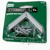
I used 2"/50mm L-Brackets screwed into the sides of the TOP HALF of the clam shell casing with self-taping screws (1/2" / 1.2cm long). This provided approximately 1cm clearance below the DCC.
What did you use for L Brackets?
 
Good Day folks,

I am starting this thread related to the Chargery DCC, so the first post will be a basic "intro". See the following posts for more info.

View attachment 21825

The DC contactor is designed specially to work with the CHARGERY BMS', the following are some features:
  • Bi-directional connection, one DCC can be used in a Common port such as a Solar system, instead of two SSR's (Solid State Relays) or conventional relays.
  • The DCC has a Built-in the surge suppressing circuit, thereby eliminating the need for the additional Relay Delay Time board which is used to avoid a surge current when starting to charge or discharge. For other SSR's or mechanical relay, please consider the surge current potentials seriously and make a suitable plan for using a delay board as applicable.
  • Over temperature protection. If internal temperatures overheats, the DCC contactor will shut off.
  • 1 Intelligent cooling fans turned on automatically

Common & Separate Port
View attachment 21826
Links:
DCC Manual:
http://chargery.com/doc/Chargery DC contactor manual V1.0.pdf
Chargery Main Site: http://chargery.com/


View attachment 26231


EDIT Sep.4.2020

A Brief History on the DCC
The DCC which is shown here is the direct result of SSR (Solid State Relay) testing performed by Craig, Myself, and a couple of others here on this forum. As we were testing SSR's and looking for High Amp capacity units we encountered various issues related to "generic" DC SSR and to be honest it was trying at best. Trying to find anything capable of 100VDC+ & 100A or more and handle big battery cable lugs was next to impossible. We even had a company make up BIG LUG SSR's of 500A & 1000A. Here is Craig's SSR Testing Thread if your interested. There were issues of Uni-Directional Contactors vs Bi-Directional ones and then of course Pre-Charging an inverter and flexibilty.

Most importantly, the real key piece was to get Contactors that used Minimal Power to operate because the original Electro-Mechanical contactors were honestly Power Hogs. They get hot and having two hot relays in the mix wasting a lot of power using up "real estate" in the installation wasn't ideal for many applications. Combining the DCC to operate in a Bi-Directional fashion like this also solved having to use an OptoCoupler to reduce from 2 Contactors to 1 Contactor in a common-port configuration which is yet another saving in power & money as well.

The Bottom Line: Jason Wang @ Chargery developed this DCC based on email discussions between Craig, Myself & others with Jason ad the testing mods we were working on. Jason Listened & Heard us and developed this DCC system based on that. How often do you run into a company that Listen's & Hear's what clients are suggesting & discussing and acting positively on that ? It says a LOT in my opinion. THIS IS VERSION 1.0, a few quirks is expected and below I show them from what I have seen so far, I am certain that Jason will address these and he's already come up with a couple of possible solutions. Even with the current "Inconvenient Quirks" I am pretty confident that these will work as intended and to that end I am putting them into my Final Production Configuration on all of my packs.

I hope you all find this thread of interest and maybe even helpful as things progress.
Have a Great Solar Day Everyone !
Steve
If you are running 48v system then the 100v/600a becomes "about" 300a correct? Or is it the 12v it uses or what?

I got to page 3 of 11. Can you please update the OP with all the latest info. Is the heat and high draw issues solved with the mechanical relays?

Do you need 2 relays? One for discharge/low voltage disconnect and one for charging/high voltage disconnect? I read someone used 2 of them.

Where do you buy these and know they are not counterfeit? Is there a full kit I can buy? Can I support someone on here?

Total noob here

Sorry
On a switch, it is either on or off, so there is very little power dissipation. Only that which is due to resistive loss in the on state. So it has a maximum voltage rating that it can handle when in the off or open state. That is the 100 volts maximum rating. Above that voltage it could arc over or otherwise damage the internal components. And it has a maximum current rating, in this case 600 amps where the current flow in the on or closed state will cause too much heat and possibly fail. The system voltage, as long as it is under 100 volts is fine, and it can handle up to 600 amps, at any voltage under 100 volts. The combination is not an issue.

If your charging sources and discharging loads are separate, it is best to use 2 separate contactors. That way the system can turn off the load when the batteries get low while still allowing the charge current to charge the batteries. Or it can disconnect the charging current when the batteries get full and still allow power to run the loads.

I do not have direct knowledge on the Chargery with a DCC to know how it handles this situation on a common inverter/charger situation. My BMS with a single port is able to act like a diode to stop either the charge or discharge current individually. It is probably covered in this 11 page thread.
What size DCC do I need:
That doesn't answer if the 100v rated relay has a lower voltage draw of 48v from your battery (roughly half) does the amperage rating go down as well do to the lower voltage? So I need to get the 600a if I'm going to draw 250a. My setup config is below.

Wait a minute, if I was drawing 6,000w off of a 48v battery vs 100v then the amps would double, not half. Right? If I decide to do 12kw at 48v = 250a. so I need a minimum 125a DCC correct?


Two DCCs or one:
The common port vs separate port confused me. I think all I have ever seen is common port, like with a daly. Can you explain why I would want two DCCs and separate port. Wouldn't that just be a higher draw?
Well a charge controller could turn off the pack if its too high, but it has no idea if each cell is too low or high. so I still think you would need two DCCs to be the safest. For example if you have just one DCC for charging and the the cell is too low and the controller keep charging the remaining cells would charge too high to compensate for the low or bad cell then turn off right? If one cell is too high and turned off by the BMS then as they discharge the high cell would inflate the others and those would discharge too low so a DCC on that end would be best also right.


Configuration:
I'm trying to find the right configuration for 16s 48v battery and 250a draw max. If the consumption is low even when in use the. Why not rate higher right. What is the consumption at 4000w on a 48v system. It looks like itnis a .13watt consumption while running 12v at 11ma = .132 watts. That seems great and the top three DCCs all seem to be 11ma

When it all arrives I will have two 16s 48v batteries, two MPP 6kw all-in-one inverters, and 50 panels. I was thinking run a Chargery to each 16s battery, then each battery will have its own MPP, then parallel them for split phase (US). If I runs the 16s as 2p then if I'm only using single phase 120v, then my ah would double if I was just using one appliance. So maybe I should do 16s2p battery. The only 240v split phase capable appliance I have is a welder and I think I would rather use a generator for that huge power draw.
 
Last edited:
The difference for wiring common/separate is the wire & requiring two DCC's. The MultiPlus is a combo unit (Inverter/Charger) like most, so there is no advantage to separate port mode. The DCC's work as they are supposed to * and so far I have not encountered problems aside with the few Version 1.0 first issues which were resolved (longer lugs and spaced wide apart). The "relay" signals can also be used via optocoupler to tell teh Multiplus to stop charge or stop invert (although I don't know the details on that, I'm no Victron user). With Victron CanBUS is the prefered way to interact with a BMS and Chargery does not do that.

There IS a catch too... It's a General One. When charging LFP and monitoring cells as it should, If one cell reached 3.65V before the other the BMS will kick charging off to protect from overcharging the one cell, even if the others are below 3.65V. Same will occur if a cell reaches 2.50V to protect from over discharge. This becomes even trickier if you have more than one battery pack & multiple BMS' !

The "Bad Part":
If say you have 3 packs in parallel, each charging away happily, A reaches Full cutoff, B sucks up the extra along with C, now C hits full and B get's the Full Load. A has now settled and is able to take charge so it enables it and & B trips because it's full. At one point all 3 will trip due to reading as full, now the Charger has a kinipshin because the batteries are "gone (disconnected by BMS), The Inverter Freaks as the battery is "gone", the whole show shuts down. 99% of the time it's a Manual Restart of the inverter, after the BMS' have enabled the batteries again. This is more pronounced with cells that deviate a great deal, the typical result of NOT Top Balancing and matching up cells.

THE above issue is a chain smoking drunk monkey that I am battling with as I am running 4 packs in parallel and tackling it to the ground has been an interesting challenge. I'm slowly working up to a software solution that reads the RS232 data from all of the BMS' on a RaspberryPi which can then take actions... my winter project. The next version from Chargery will likely have a few extras to make life a bit better.

For Victron There are BMS' which will work that have interfaces to their GX stuff and more. REC Bms, TinyBMS & Orion do I believe, as well some of teh Bestech BMS' do too. None of these are cheap BTW. There may be others.
I would buy your parallel pack overseer. It seems to me that 16s BMS is the max you get these days at a decent price vs for example Batrium. You idea would allow many people to start building larger systems with the eve and Lichen cells that are currently cheap.
 
Sorry but I have no clue what you are trying to say.

Chargery OLD WEBSITE :
CHARGERY is professional manufacturer for top quality RC and eVehicle power products including chargers,balancers,adapters and balance chargers

Chargery NEW SITE (site certificate needs to be corrected yet) :
CHARGERY is professional manufacturer for top quality RC and eVehicle power products including chargers,balancers,adapters and balance chargers (chargerystore.com)

Vendors like LUYUAN are Authorised Vendors as well as others, including ICoGOGO.

Then you have Rebranded (House Branded) ones like these:
Choice BMS Battery Management System | Electric Car Parts Company
BlueBIRD BMS – BobolinkSolar
I just was saying that a link to their store in the OP would be great. :)
 
Has anybody done any voltage/current measurements on their DCC? I'm interested in the voltage drop from input to output of DCC when loaded with appreciable current under these conditions:

1. Normal operation (no faults). Measure load current and DCC voltage drop
2. BMS over voltage fault. Measure load current and DCC voltage drop
3. BMS under voltage fault. Measure charging current and DCC voltage drop

A simple way to simulate a fault is to open either the OVP or UVP wire to the DCC.
 
I just got a package from Jason which included the new External Power Adapters for the BMS', installed them this morning and the voltage readings and such have really settled down nicely. It is making a difference in the internal passive balancing as well as it reads values more sensibly. At present I am pushing 135A charge into the bank and eagle eyeing it.

I was also sent the ISO Board adapter to put between the DCC & BMS for (+) line Operation. I have not installed those at this time as I am wired to use the DCC on the NEG line per the original instructions as provided by Jason. I may test this when I assemble the next pack to go into place, as my LFP bank is production, so I can't / won't futz much with it. Ain't broke don't fix it. It also means cutting up more of my 4/0 cabling and crimping on more lugs and to be honest, I've had to spend Far More on wire than I ever intended to with all the changes.

@Cal, if you want, I can do some quicky tests with a DMM if you specify what exactly you'd like to see... step-by-step instructions. The current charge run on the bank will run another 3.5-4.0 hours yet.... I bottomed the whole bank to just tickling 0% SOC on all packs, prior to this charge run. Once this part is done (the LFP's), I'll be running a Deep Charge on my FLA Bank for 4 hours, so the day is accounted for.

BTW: Using BMS8T-300's with 1st issue 300A DCC's on the Negative Line after the Shunt. (Batt to Shunt to DCC to Common DC Busbar and out)
.
 
if you want, I can do some quicky tests with a DMM if you specify what exactly you'd like to see... step-by-step instructions.

Unfortunately the easiest way to run this test is to open the two fault wires coming from BMS, going to DCC. Once the wires are cut, insert a toggle switch in the two locations to complete the circuit again. Now you can simulate an over voltage or under voltage situation by opening the switch.

While the DCC is conducting current (either charge or discharge), measure the voltage drop across the DDC as I described in my previous post. You'll be measuring a voltage drop that might be less than 0.1V. The greater the current the greater the voltage drop. Need to record voltage drop and current.
 
You would only be non-operational for a minute, until the toggle switch is installed. Then another minute after test is complete to remove switch and re-solder wires together & insulate exposed solder connection.

Don't need to cut fault wires for a partial test. You can place cell temperature sensor in ice water. You should have plenty of that. The BMS will throw an over voltage fault (disabling charging). Apply a sizable load current and measure voltage drop across DDS.

You just can't measure how the DDS reacts to a under voltage fault.
 
You can place cell temperature sensor in ice water.
Hahaha.. NOT. That would mean disassembling battery cases which have the cells compressed into them, tearing the packs apart to extract the sensors from between the cells is not happening. I have extra wires harness bits that I could make a replacement "wireset" with switches IF I had spare switches which I don't and those are 45 minutes 1-way away. The LFP bank is now at 27.5V and still climbing, so not stopping that till it's done. The saturation point should be reached within the hour, after which time, I'll give it 30-45 minutes for Topping then I have to flip over to Lead Bank Charging.

Maybe next time.

PS: Having 7 Days of Live Reserve is great BUT can be a PITA at some times.... More Panels & SCC in spring, seems like I just don't have a choice now.... especially after the next 280 goes online.
 
Is the ambient temp sensor easier to get too? I believe a large temperature difference will also disable charging. Do you still have the cables from the defective BMS? You could swap out the sensors and get easy access.

Or, anybody else up the the challenge?
 
Cal, if you look at my "About my System" page, you may realize that for me it's just not a simple task anymore. Those pictures are "close" to what's there now, it got a wee bit more complex and interconnected.

I will only have one more opportunity to rearrange things once the next pack is ready & by then I'll also have to decide what to do about the pair of 174's (which came originally as 1, 24V/350AH pack with paralleled used cells, that I may have to put back into paralleled cell config.
 
Back
Top