Can you look at individual cell voltages, may have a runner which is causing the BMS to go into OVP. Assume there is a passive or active balancer in those batteries.Well jyeah mine was working with just 7,8 I added 3,6 back in and didn't see any difference.
But my full all 8 cable was working for a week and then I got an error 58..
You are using an out of date browser. It may not display this or other websites correctly.
You should upgrade or use an alternative browser.
You should upgrade or use an alternative browser.
Install and Operation of the SUNGOLD 10KW 48V SPLIT PHASE SOLAR INVERTER
- Thread starter Kenny_
- Start date
Kenny_
Solar Wizard
It's @Lighthouse Beacon having that issue ?Can you look at individual cell voltages, may have a runner which is causing the BMS to go into OVP. Assume there is a passive or active balancer in those batteries.
Last edited:
Kenny_
Solar Wizard
Here's the response from Sungold wrt my not seeing multiple batteries.....this is the communication problem in dealing with them. What do you suppose this answer means?
--------------
Dear Customer,
Wish you the best day.
You are not seeing any indication that there are two batteries connected, that's normal, because your inverter and battery didn't build BMS communication.
If you want to see battery capacity or battery number, you need to build the inverter and battery BMS communication. Currently, your inverter and battery don't build BMS communication. BMS communication is a choice, not a necessity.
--------------
--------------
| 5:25 AM (2 hours ago) | ||||
|
Dear Customer,
Wish you the best day.
You are not seeing any indication that there are two batteries connected, that's normal, because your inverter and battery didn't build BMS communication.
If you want to see battery capacity or battery number, you need to build the inverter and battery BMS communication. Currently, your inverter and battery don't build BMS communication. BMS communication is a choice, not a necessity.
--------------
Hedges
I See Electromagnetic Fields!
- Joined
- Mar 28, 2020
- Messages
- 21,806
Per Cindy ?
Now im more confused than ever
"There is nothing wrong with the custom cable you made that only has pins 7 and 8."
It is going to be beyond the understanding of customer support people, but they ought to be given clear information.
But really, there should simply have been a schematic of the correct cable, rather than two paragraphs saying what to leave connected and what to disconnect, while remaining silent about pin #6 ground.
RS485 Data+ and Data- are differential. They ought to be driven in opposite directions, so little to no return current has to go through ground. Will also work if just one is driven and other is held steady, because there is still a differential voltage between them, but that does push current elsewhere.
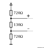
In a 5V system, three resistors in series between +5V and ground (or reference plane of circuit, not necessarily tied to earth ground) could be 1500 ohm, 100 ohm, 1500 ohm. 5V / (1500 + 100 + 1500) = 1.6 mA
1.6 mA x 100 ohm = 0.16V differential between data+ and data-
Common mode, they are centered about 2.5V, data+ is 2.66V, data- is 2.34V, allowing a couple volts offset or noise between devices while keeping the voltage in a range receiver can use. Unlike logic levels referenced to ground, where an offset in ground changes logic level.
Both ends have 100 ohm resistor, because a twisted pair of wires has about 100 ohms characteristic impedance. Any signal propagating down the wires is absorbed by the resistor, doesn't reflect back and get seen as another pulse.
Similar resistor values shown here:
RS-485 - Wikipedia

RS-485: How To Correct The Bus Signal Polarity Of Cross-Wired Data-Links
TI's Thomas Kugelstadt offers a number of technical fixes for RS-485 bus signal polarity correction (POLCOR) in industrial control systems. POLCOR used to be rare. Now, it results...
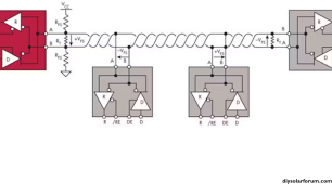
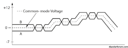
Common mode voltage can vary. But if it goes beyond power rails of receiver then it doesn't work:
Understanding RS-485 Interface Communication - Janitza®
Explore the benefits of the RS-485 communication protocol, including resistance to EMC interference and ease of configuration.
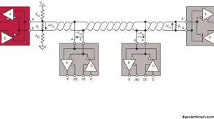
Ground should route with data+ and data-, ideally as a shield around them or at least another wire twisted with them.
data+ and data- are a pair of wires twisted together, which gives them 100 ohm differential impedance (more capacitance and less inductance when driven apart from each other). They interact less with ground.
Serial Communications | iKnow Knowledge Base | Invertek Drives | Invertek Drives

I don't worry about ground loops in AC power distribution, like ground wires in multiple conduit which come back together at another box and conduit also carries current. But the "ground" reference of logic, like "0V" in above diagram which goes from PCB in one box to PCB in another box, should not form a loop with AC power system. It is OK if just one device has it's PCB reference plane grounded, but if two do then AC ground current will flow through them and upset the data with common-mode voltage. Generally all logic and analog should be isolated from ground in most places. But you're stuck with whatever the vendors did inside. (Finding and fixing those things if designers did otherwise is my job at work.)
I once got a schematic from a colleague, an EE new hire in Bangalore. It had I2C data and clock wires between socket or board under test and header for USB/I2C adapter. I told him he should also connect the ground plane. He said it didn't need ground, got it from USB. When he visited some months later he gave me a test fixture board, which had copper wire added for ground. It might have sort of worked without that, if USB shield providing ground through a huge loop of wire, but subject to noise.
After that, he debugged and got working an RF amplifier board supplied by a vendor, following what he learned studying the RF board I designed. Sharp guy!
Partimewages
Solar Addict
You ordered the wrong thing?
Kenny_
Solar Wizard
Not sure if this is addressed to me or someone else??You ordered the wrong thing?
Hedges
I See Electromagnetic Fields!
- Joined
- Mar 28, 2020
- Messages
- 21,806
Here's the response from Sungold wrt my not seeing multiple batteries.....this is the communication problem in dealing with them. What do you suppose this answer means?
If you want to see battery capacity or battery number, you need to build the inverter and battery BMS communication. Currently, your inverter and battery don't build BMS communication. BMS communication is a choice, not a necessity.
Over here, "Build" is a term for software compilation and linking. But maybe she just means build a cable. Your inverter does see the first battery, correct?
Possibly, inverter has to be configured with multiple batteries. When the first system was brought up, maybe it went through RS-485 looking for connected devices. That's what my SMA monitoring equipment does. Is there a way to restart system configuration?
Kenny_
Solar Wizard
Well, yeah.... I'm thinking he means 'building' the cable but maybe a software thing... I have at least once shut everything down and restarted. The no configuration to be done wrt to battery configuration other than specifying type of battery number of cells and bms communication type which I set per the instructions given to @Lighthouse Beacon ...Over here, "Build" is a term for software compilation and linking. But maybe she just means build a cable. Your inverter does see the first battery, correct?
Possibly, inverter has to be configured with multiple batteries. When the first system was brought up, maybe it went through RS-485 looking for connected devices. That's what my SMA monitoring equipment does. Is there a way to restart system configuration?
I'm think the inverter just doesn't do/know/display anything about the battery packs/configuration, it's just working with volts, amps, state of charge.
I'm going to hopefully get the Solar Assistant talking directly to the batteries BMS in the next day or so....whenever I get that cable from SA or the one from Amazon
Lighthouse Beacon
Following the Light
It is going to be beyond the understanding of customer support people, but they ought to be given clear information.
But really, there should simply have been a schematic of the correct cable, rather than two paragraphs saying what to leave connected and what to disconnect, while remaining silent about pin #6 ground.
RS485 Data+ and Data- are differential. They ought to be driven in opposite directions, so little to no return current has to go through ground. Will also work if just one is driven and other is held steady, because there is still a differential voltage between them, but that does push current elsewhere.
In a 5V system, three resistors in series between +5V and ground (or reference plane of circuit, not necessarily tied to earth ground) could be 1500 ohm, 100 ohm, 1500 ohm. 5V / (1500 + 100 + 1500) = 1.6 mA
1.6 mA x 100 ohm = 0.16V differential between data+ and data-
Common mode, they are centered about 2.5V, data+ is 2.66V, data- is 2.34V, allowing a couple volts offset or noise between devices while keeping the voltage in a range receiver can use. Unlike logic levels referenced to ground, where an offset in ground changes logic level.
Both ends have 100 ohm resistor, because a twisted pair of wires has about 100 ohms characteristic impedance. Any signal propagating down the wires is absorbed by the resistor, doesn't reflect back and get seen as another pulse.
Similar resistor values shown here:
RS-485 - Wikipedia
en.wikipedia.org
View attachment 176383

RS-485: How To Correct The Bus Signal Polarity Of Cross-Wired Data-Links
TI's Thomas Kugelstadt offers a number of technical fixes for RS-485 bus signal polarity correction (POLCOR) in industrial control systems. POLCOR used to be rare. Now, it results...www.electronicdesign.com
View attachment 176384
Common mode voltage can vary. But if it goes beyond power rails of receiver then it doesn't work:
Understanding RS-485 Interface Communication - Janitza®
Explore the benefits of the RS-485 communication protocol, including resistance to EMC interference and ease of configuration.www.janitza.com
View attachment 176386
Ground should route with data+ and data-, ideally as a shield around them or at least another wire twisted with them.
data+ and data- are a pair of wires twisted together, which gives them 100 ohm differential impedance (more capacitance and less inductance when driven apart from each other). They interact less with ground.
Serial Communications | iKnow Knowledge Base | Invertek Drives | Invertek Drives
www.invertekdrives.com
View attachment 176387
I don't worry about ground loops in AC power distribution, like ground wires in multiple conduit which come back together at another box and conduit also carries current. But the "ground" reference of logic, like "0V" in above diagram which goes from PCB in one box to PCB in another box, should not form a loop with AC power system. It is OK if just one device has it's PCB reference plane grounded, but if two do then AC ground current will flow through them and upset the data with common-mode voltage. Generally all logic and analog should be isolated from ground in most places. But you're stuck with whatever the vendors did inside. (Finding and fixing those things if designers did otherwise is my job at work.)
I once got a schematic from a colleague, an EE new hire in Bangalore. It had I2C data and clock wires between socket or board under test and header for USB/I2C adapter. I told him he should also connect the ground plane. He said it didn't need ground, got it from USB. When he visited some months later he gave me a test fixture board, which had copper wire added for ground. It might have sort of worked without that, if USB shield providing ground through a huge loop of wire, but subject to noise.
After that, he debugged and got working an RF amplifier board supplied by a vendor, following what he learned studying the RF board I designed. Sharp guy!
Brilliant @Hedges that does make sense. After reviewing your first mention of the needing PIN 6 I did think along similar lines, but thought it would just equate to more inductance possibly but not effect the communication protocol. I am moving towards peak solar input part of the day and am curious to see if I error out BMS Comm failure and OVP battery alarm. I still won't see how not having the ground attached could somehow relate to the BMS accepting overcurrent to the batts until OVP faults.
Ive told Inverter parameters to:
Reduce bulk battery charging from 57.6 to 55.2
Reduce Battery Float Charging from 55.2 to 54.8
Reduce battery Overdischarge voltage from 40 (default) to 46.4
In an attempt to not "top of the knee" as @42OhmsPA mentioned.
My goal is to not error out when my panels are exceeding output that my house can take, and my battery is at 100% SOC.
Lighthouse Beacon
Following the Light
I plan to copy you on this strategy @Kenny_Well, yeah.... I'm thinking he means 'building' the cable but maybe a software thing... I have at least once shut everything down and restarted. The no configuration to be done wrt to battery configuration other than specifying type of battery number of cells and bms communication type which I set per the instructions given to @Lighthouse Beacon ...
I'm think the inverter just doesn't do/know/display anything about the battery packs/configuration, it's just working with volts, amps, state of charge.
I'm going to hopefully get the Solar Assistant talking directly to the batteries BMS in the next day or so....whenever I get that cable from SA or the one from Amazon
Kenny_
Solar Wizard
Sorry for high jacking your thread @Kenny_
I changed the name of this thread to "the" instead of "my" we can just use it as a collective Q&A Operation/etc thread if you all want. No problems. We can share/collect info on this beast.
Lighthouse Beacon
Following the Light
Thanks @Kenny_ I am sorry to keep coming in here with my troubles, but like you said this will probably help each other and will help others in the future who "Google" their way in here with issues.. I know that's been me in the past.. and with these Sungold branded products not having alot of web history alot of this discussion is foundational for new SG device folks i'd thinkI changed the name of this thread to "the" instead of "my" we can just use it as a collective Q&A Operation/etc thread if you all want. No problems. We can share/collect info on this beast.
Kenny_
Solar Wizard
I'll add a little note to the first post....
Kenny_
Solar Wizard
No I consider all these threads shared! And this way we can all learn more about our machines.Thanks @Kenny_ I am sorry to keep coming in here with my troubles, but like you said this will probably help each other and will help others in the future who "Google" their way in here with issues.. I know that's been me in the past.. and with these Sungold branded products not having alot of web history alot of this discussion is foundational for new SG device folks i'd think
Hedges
I See Electromagnetic Fields!
- Joined
- Mar 28, 2020
- Messages
- 21,806
You're already hacking cables anyway. You could try assembling a multi-drop cable with all plugs in parallel. Plug it into inverter and multiple batteries. Keep the stubs to plugs along the way as short as possible.
Hmm, but since they meant these to be daisychained with separate jacks, if they don't mention terminators, probably each jack has its own 100 ohm resistor. With no other boxes connected, just a pigtail cable coming out, check voltage (around 0.1V?) when turned on. If no voltage, or when off, check resistance (around 100 ohms?) That's between Data+ and Data-. Also check voltage and resistance of each to ground.
While there is no cable between the boxes, check voltage between their RJ45/RS-485 grounds. Check resistance.
Ideally, somebody with a scope would probe Data+ and Data- with two single-ended probes.
Hmm, but since they meant these to be daisychained with separate jacks, if they don't mention terminators, probably each jack has its own 100 ohm resistor. With no other boxes connected, just a pigtail cable coming out, check voltage (around 0.1V?) when turned on. If no voltage, or when off, check resistance (around 100 ohms?) That's between Data+ and Data-. Also check voltage and resistance of each to ground.

While there is no cable between the boxes, check voltage between their RJ45/RS-485 grounds. Check resistance.
Ideally, somebody with a scope would probe Data+ and Data- with two single-ended probes.
Partimewages
Solar Addict
It was. I don't know if the have different configurations from factory or not. Just a thought, but @Hedges might be on to somethingNot sure if this is addressed to me or someone else??
Kenny_
Solar Wizard
Thanks. I'm thinking I'm going to standby til I get the cable to connect directly between the Raspberry Pi/Solar Assistant and the Battery/BMS and then go from there.It was. I don't know if the have different configurations from factory or not. Just a thought, but @Hedges might be on to something
In the mean time I'm thinking seriously about the install and at least for the moment am thinking of installing this all my utility room. Essentially where it is right now mounted on the wall above the table it is on. Batteries on the rack under or near. This means I'll have to run new wire/conduit etc from the garage to this location for the direct connect to the inverter. I'm currently running with what is essentially an extension cord 30 A but still just that running out of the utility room window around the patio and into the garage to plug into the transfer switch. I'd run the conduit and wiring a more permanent install but will require running it in the office ceiling above my desk etc. It will be a major pita. Still it's probably the right/best way to do it.
Will keep you posted.
P.S. There is an unused 220 plug (former air conditioner) just above the wall where I'd mount the Inverter. I would run that run from that plug (turn it into a junction box?) down into the basement and use that as the AC Input for the inverter. Should work fine (about the same as the dryer plug but more permanent/certifiable I hope).
Here's a couple of pics of the mess.
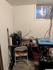
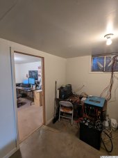
Lighthouse Beacon
Following the Light
You're already hacking cables anyway. You could try assembling a multi-drop cable with all plugs in parallel. Plug it into inverter and multiple batteries. Keep the stubs to plugs along the way as short as possible.
Hmm, but since they meant these to be daisychained with separate jacks, if they don't mention terminators, probably each jack has its own 100 ohm resistor. With no other boxes connected, just a pigtail cable coming out, check voltage (around 0.1V?) when turned on. If no voltage, or when off, check resistance (around 100 ohms?) That's between Data+ and Data-. Also check voltage and resistance of each to ground.
View attachment 176404
While there is no cable between the boxes, check voltage between their RJ45/RS-485 grounds. Check resistance.
Ideally, somebody with a scope would probe Data+ and Data- with two single-ended probes.
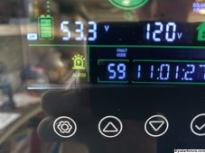
Got home to batts in OVP status and inverter throwing 59. Cable with grounds didn’t fix the problem. Inverter ID changes didn’t stop the problem. I even kept a mini split on try to suck some power off the panels but it still overcharged the SG powerwall. I hear the BMS clicking when this happen. And run light flashes off and on, status goes discharge/charge/discharge/charge
I am disabling BMS comms now and draining the batt down to see what it does as it recovers
Lighthouse Beacon
Following the Light
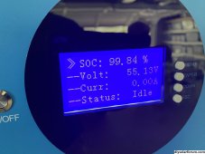
Disabled BMS comms and powered whole system down. Brought it back online with ID32 SLA (no BMS comms or wire)View attachment 176436
Got home to batts in OVP status and inverter throwing 59. Cable with grounds didn’t fix the problem. Inverter ID changes didn’t stop the problem. I even kept a mini split on try to suck some power off the panels but it still overcharged the SG powerwall. I hear the BMS clicking when this happen. And run light flashes off and on, status goes discharge/charge/discharge/charge
I am disabling BMS comms now and draining the batt down to see what it does as it recovers
And it charged back to my ID09 set Bulk charge of 55.2 and stopped charging the batts at 55.2V Didn’t catch an OVP.
Something is wrong with SPH10K48SP and SG48100M inverter/BMS comm data/protocols out of box on these units.
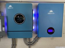
Lighthouse Beacon
Following the Light
@Kenny_ you are a mad scientist!!Thanks. I'm thinking I'm going to standby til I get the cable to connect directly between the Raspberry Pi/Solar Assistant and the Battery/BMS and then go from there.
In the mean time I'm thinking seriously about the install and at least for the moment am thinking of installing this all my utility room. Essentially where it is right now mounted on the wall above the table it is on. Batteries on the rack under or near. This means I'll have to run new wire/conduit etc from the garage to this location for the direct connect to the inverter. I'm currently running with what is essentially an extension cord 30 A but still just that running out of the utility room window around the patio and into the garage to plug into the transfer switch. I'd run the conduit and wiring a more permanent install but will require running it in the office ceiling above my desk etc. It will be a major pita. Still it's probably the right/best way to do it.
Will keep you posted.
P.S. There is an unused 220 plug (former air conditioner) just above the wall where I'd mount the Inverter. I would run that run from that plug (turn it into a junction box?) down into the basement and use that as the AC Input for the inverter. Should work fine (about the same as the dryer plug but more permanent/certifiable I hope).
Here's a couple of pics of the mess.
View attachment 176420View attachment 176422
Kenny_
Solar Wizard
That's what it seems like!!
To both of the above?
To both of the above?
Quattrohead
Solar Wizard
Also note that RS485 does not need the ground / shield and indeed my HVAC system docs explicitly tells you to only connect it at one end if you do use it.
Kenny_
Solar Wizard
That's my subjective experience as well with this inverter/battery comm cable...Also note that RS485 does not need the ground / shield and indeed my HVAC system docs explicitly tells you to only connect it at one end if you do use it.
Kenny_
Solar Wizard
Oh so now I've got another WTF? I was reading the instructions in the email I was sent and it says
"
Here are steps to build BMS communication between the inverter and battery, please check:
1. Custom-made a BMS cable for the inverter and battery. ( The battery comes with a BMS cable, but you need to make some adjustments to the cable terminal)
For the inverter: pin7 is RS485-A, pin8 is RS485-B,
For the battery in2 (or7) is RS485-A, pin1(or 8) is RS485-B,.
"
I think what he is saying is that pin 7 of the inverter plug connects to pin 2 of the battery and 8 of inverter to 1 of the battery...
This seems to match the cable shipped with the inverter (i.e. the pins are reversed) but the battery cable and the cable I modified are straight-through 1-1 8-8,
But see he has (or7) in parathesis which is what is screwing the pooch!
I'm gonna try it with reversing the pins ....
"
Here are steps to build BMS communication between the inverter and battery, please check:
1. Custom-made a BMS cable for the inverter and battery. ( The battery comes with a BMS cable, but you need to make some adjustments to the cable terminal)
For the inverter: pin7 is RS485-A, pin8 is RS485-B,
For the battery
"
I think what he is saying is that pin 7 of the inverter plug connects to pin 2 of the battery and 8 of inverter to 1 of the battery...
This seems to match the cable shipped with the inverter (i.e. the pins are reversed) but the battery cable and the cable I modified are straight-through 1-1 8-8,
But see he has (or7) in parathesis which is what is screwing the pooch!
I'm gonna try it with reversing the pins ....
Hedges
I See Electromagnetic Fields!
- Joined
- Mar 28, 2020
- Messages
- 21,806
Try pins 7 & 8 as RS485 into battery #1. Pins 2 & 1 as RS485 out of battery #1, feed on to battery #2.
Check voltage & polarity of each of these pairs. Especially on pins 2 & 1 when the cable is connected from inverter to battery.
Is there any talk of terminators, or jumpers to connect terminators?
If pin 7 is wired to pin 2, and pin 8 is wired to pin 1, I'd expect a way to terminate or not, depending on whether it will daisy chain further.
Similar threads
- Replies
- 499
- Views
- 21K
- Replies
- 13
- Views
- 432
- Replies
- 2
- Views
- 314
- Replies
- 1
- Views
- 403


