Welcome to the New Year.
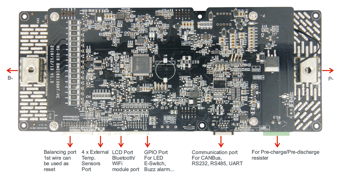
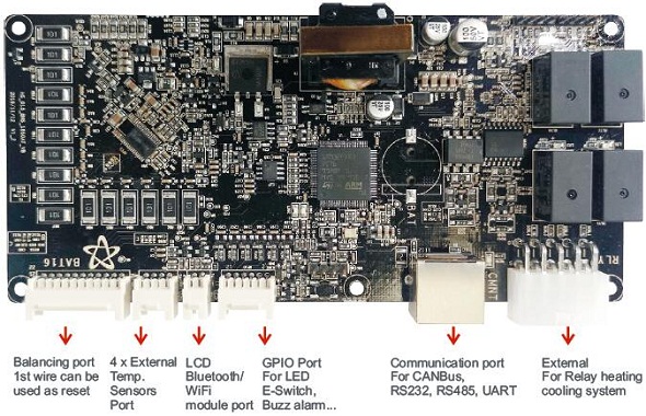
After all the great discussion on this tread, I did purchase the BigBattery 24V 170Ah LiFePO4 Power Block
The box did not come with any documentation at all. I have made numerous requests via live chat and emails to BigBattery (including
@MrGreen ) with only one response saying that they have no digital version they can email.
So I am looking for the configuration parameters for my charge controller (using GroWatt 24v 3000W unit). These numbers should be applicable to any other charge controllers I would think. In addition the voltages would help with the
Solar Battery Monitor as seen in this video
I am using
@Will Prowse published settings for these all-in-one units, but it still calls for specifics for the battery being used.
My requests/questions are:
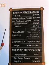
- What is the low voltage disconnect of the BMS?
- What is the over voltage set at?
- What is the Floating Charge Voltage?
- What is the Bulk Charge Voltage?
- For a Battery Monitor Voltmeter, what is 100% SOC volts and 0% volts?
Referenced Links
BigBattery 24V 170Ah LiFePO4 Power Block
GroWatt 24v 3000W unit
AiLi Battery Monitor Voltmeter