diy solar

diy solar

Solar house generator I started DIY back in 2000 - My path from Trace to Xantrex (on FLA battery) to XW Pro inverters on Tesla Model S batteries

Thanks for sharing. Obviously you ARE a serious hobbyist! Your updating and "cleaning up" of wiring etc. is awesome.d
Good luck down the road.


yeah I guess so
can't chase skirts for various reasons, so this keeps me home
thanks

I am a software geek, and I love the tech in this "hobby with benefits", especially as it has evolved over the past 20 years.

One of the benefits is below
Today is the last day of this past month's billing cycle, here is the LAST MONTH's break down for the next bill


Bought-kwh
Generated-kwh
Percent of power Generated at home
306​
492.37​
61.67%
0.0833​
$25.49​
$41.01
Savings to the left
$13.70​
$3.58​
$42.77​
$83.78​
What my bill would be without solar​

.0833 is the dollar cost per kwh
$25.49 is what I paid for the energy I bought
$13.70 is the monthly fee - will never go away, but will rise to $15.50 in a couple of years
$3.58 is the various taxes

Next month we shall see the effect the extra panels have on the grid bill

Instead of buying a $50,000 pickup, I spent $17,000 to rebuild a 1984 GMC K1500 pickup (avatar pic) with a 2002 Silverado LS 5.3 engine, and built a $20,000 solar generator over the pass 20 years and I am still ahead.
Both have nice "benefits"
 
Last edited:
In 1999 I scheduled and attended a solar design and implementation class put on by SEI www.solarenergy.org based in Colorado. I took a 1 week class in Washington. The class I took was
PV101: Solar Training – Solar Electric Design and Installation

back then it was focused on battery based system. Today the above class focuses on GRID-TIE systems without batteries. Advanced classes touch on battery based generators


Well I wanted an UPS/battery based system. Uninterrupted Power Supply system. When the grid drops, my system would continue to operation. I had computer servers to run at home.


I didn't (still don't) want a GRID-TIED solar generator. When the GRID drops, then no power to the house not withstanding thousands of watts of power panels on the roof. SO batteries have always been a part of my plan and implementation. But batteries are the dirtiest part of solar generators.


After this class I came home with lots of new knowledge and passion and put together a system plan then began to allocation the monies for it, as well as plans for where to put things. I slowly and concurrently rebuilt the old garage from cinder block walls to 2x6 stick walls (without removing the roof - that was fun) with a good new foundation. How I did that is an other story. But in this new building I housed the first major system I built. The following covers the PROCESSING equipment for my system. This includes controllers, inverters, meters, wires, breakers, conduit and the like.


First pic:

On the far right is the Ground Fault breaker system. If any current hits the ground wires, this will trip OFF all incoming PV power

View attachment 15

Center is the 250 Amp breaker from the batteries to the inverter. Above that center, is the RV Power Products Solar Boost 50 (SB50) which is the controller for Array #1 of solar panels. 24 volt incoming design. I am still using this charge controller today


On the left is the Trace SW4024 inverter. Works on a 24 volt battery bank and produces 120 volt AC power (just one leg).
Nice inverter with all types of configuration menus. Still working today


The meter on the upper right is a battery monitor meter, and measures how many amps are going to/coming out of the battery. Like a gas tank gauge, but for the battery. Did not like this version, later I got a new/better user interface one.

The second picture is the inside of the MPPT charge controllerView attachment 19

I love your old school build! I have a question that this build can apply for me...

You have a outback GFDI breaker from your PV array. This detects ground faults correct before it goes into your charge controller. I want this on my system as it seems no one has brought up a practical way to implement this safety feature.

It is missing on chinese off grid inverters like MPP solar. Id like to know how its wired on your system.

Thank you!
 
as I have reported on progress on my solar house generator, well this week I achieved a goal I have been working on for 27 years.
The system has not had to re-connect to the grid to charge the batteries.....This means that.....

I can completely power my house by solar. I am off-grid (with limitations) and use the grid for backup now.
Achieved that this week when I added an array 3 to my panels. Brings my capacity to 4.2kw of solar panels, effective production is 3.5kw from that. In the winter it should be higher due to cooler temperatures

I don't need the grid to run the solar panels. 98% of solar installations in the USA today MUST have the grid present to work - AT ALL. Lose the grid and your solar panels have no grid to sync to and they TURN OFF. I am DC coupled, being the panels charge my battery. Most installations are AC coupled and require a grid to sync to in order to generate power

The new array is installed temporarily at the moment, but the array will be moved to the house's roof shortly and be permanent. Right now it is in the "corn patch" on the ground, but it works!

I have a condition that must be met in order to achieve this goal. It must be full sun throughout the day and the next and the next..... The battery can run the house all night until the sun comes up and recharges. Lather, rinse, repeat.

Other plans include adding more solar panels AND more batteries in the coming days to provide greater than 1 day of running storage. When that is accomplished, then I hope to have capacity for 3-5 days of energy in the battery, without the sun - like cloudy days and storms. When the grid goes down in the future, I hope to be able to have some power going forward totally from the sun. (yes, yes, still dependent on the sun and clear skies, but now the beginnings of being indenpent)

Just took 27 years to get there....due to cash flow going to other needs and small stuff like that
But it feels good.
 
I love your old school build! I have a question that this build can apply for me...

You have a outback GFDI breaker from your PV array. This detects ground faults correct before it goes into your charge controller. I want this on my system as it seems no one has brought up a practical way to implement this safety feature.

It is missing on chinese off grid inverters like MPP solar. Id like to know how its wired on your system.

Thank you!

thank you

Today the Schnieder-Electric charge controller Conext 60 150 that I use now, has a 1 AMP fuse connected to ground housed in the bottom of the controller. When that fuse blows the controller will disconnect the array from the system. Since I have 3 (soon to be 4) controllers, the manual says to remove all but one of the fuses from the controllers and disable the feature on the secondaries. When there is a ground fault, the primary messages all the secondaries of the event and they all disconnect, thereby disconnecting all arrays of solar panels.

Here is the old GFDI of my old system. Is this what you are referring to?

2012-07-09_21-49-19_520.jpg

My old system (above) had this complete panel of breakers which had a connecting bar between all the breaker switches for the incoming arrays AND also connected to a 1 AMP breaker switch. When that 1 AMP detected a ground fault, it tripped which tripped all the other array breakers.

The 1 AMP breaker is the breaker in the middle and was a singe point of ground contact and it used the 1 array breaker for the fault detection. It had room for 4 breakers one for each of 4 arrays. This was the Trace Engineering product. Outback was formed by a group of engineers who left Trace back in the day

After I got the Conext controllers installed, I refactored that older box to simply be a manual disconnect point with 60 amp breaker for each array. The older system consisted of breakers that were custom to that 20 year old product and I could not upgrade with more breakers - I had 2 and needed 4.

And since the Conext system had the feature (albeit not documented completely) I moved to the new system

I can see that the "new" systems don't have the ground fault detection - at least I haven't seen it and it appears neither have you, for their internal MPPT controllers.

A good point to point out, thank you. But I don't have a solution for that unless Outback still carries the product.

dougbert

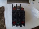
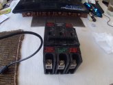
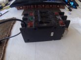
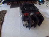
PS Here are pics of the 3 breakers

P1000001.JPG

P1000002.JPG

P1000003.JPG

P1000004.JPG

Hey you want these breakers?

PM sent

cover my shipping - lets talk via email.
 
Last edited:
thank you

Today the Schnieder-Electric charge controller Conext 60 150 that I use now, has a 1 AMP fuse connected to ground housed in the bottom of the controller. When that fuse blows the controller will disconnect the array from the system. Since I have 3 (soon to be 4) controllers, the manual says to remove all but one of the fuses from the controllers and disable the feature on the secondaries. When there is a ground fault, the primary messages all the secondaries of the event and they all disconnect, thereby disconnecting all arrays of solar panels.

Here is the old GFDI of my old system. Is this what you are referring to?

View attachment 19463

My old system (above) had this complete panel of breakers which had a connecting bar between all the breaker switches for the incoming arrays AND also connected to a 1 AMP breaker switch. When that 1 AMP detected a ground fault, it tripped which tripped all the other array breakers.

The 1 AMP breaker is the breaker in the middle and was a singe point of ground contact and it used the 1 array breaker for the fault detection. It had room for 4 breakers one for each of 4 arrays. This was the Trace Engineering product. Outback was formed by a group of engineers who left Trace back in the day

After I got the Conext controllers installed, I refactored that older box to simply be a manual disconnect point with 60 amp breaker for each array. The older system consisted of breakers that were custom to that 20 year old product and I could not upgrade with more breakers - I had 2 and needed 4.

And since the Conext system had the feature (albeit not documented completely) I moved to the new system

I can see that the "new" systems don't have the ground fault detection - at least I haven't seen it and it appears neither have you, for their internal MPPT controllers.

A good point to point out, thank you. But I don't have a solution for that unless Outback still carries the product.

dougbert

PS Here are pics of the 3 breakers

View attachment 19464

View attachment 19465

View attachment 19466

View attachment 19467

Hey you want these breakers?

PM sent

cover my shipping - lets talk via email.
Yes. This is what im talking about. Ill PM you.
 
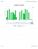
Report from my utility company on consumption on a daily basis. here there are the last 4 days (ending on the 10th) where the grid was not connected to. And today looks like it will be same

Nice to see the self generation is working


foo.jpg
 
Cloudless past 7 days today, and I expect today also will be the 7th without grid connection as well. Next 4 days expected to fully sunny. By the time the sun goes goes, SoC reaches 96-100% (with sometimes a couple of hours of water heating - when the battery is full). Battery gets down to 45 to 50% SoC by morning. Grid kicks in around 25%

this is really cool
 
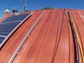
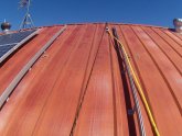
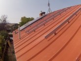
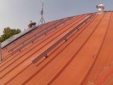
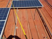
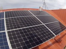
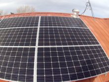
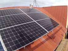
Amid the heat wave here, finally got back to the roof, installing more UNIRAC mounting rails for Array 3

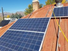
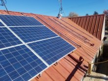
array 2 panels on the left installed 2016

here left to right are the first 2, and the last 2 going on to the right in the empty space

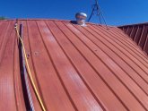
It is a 90 year old house, but I don't know when the metal roof was installed. Paint fading. Now the panels will shield the metal from some of the sun and reduce heat going into the attic

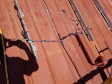
Yellow body harness rope attached to the equipment rope for now. To the left and right along the roof ridge are 2 harness hooks nailed down under the ridge cap. A third hook will be installed to the far left at the left most peak so I can work safely on the west panels to the left of the chimney (that needs mortar repair)

NOTE the left air vent whirly-bird color. The old one (24 years old) began having bearing squeak and my local
HomeDepot only had the wood color one. Oh well, my wife stopped complaining about "that noise"

P1000006.JPG

left harness hook above right line of the panel of array 2
right harness hook near the air vent on the right.
Wish I had had put a hook in the middle between the two, so I didn't need the bowline knot on the equipment rope

P1000005.JPG


I start at the top of the mounts by lag bolting them to the raw 2x4s in the attic
On these last 3 mounts, I found it the best to drill from inside the attic to the outside, by centering the pilot hole so many inches down from the ridge. It becomes a direct hit to the stud this way, and shows an exit hole on top for placement and ensures the panels will be securely mounted.

This old guy moves SLOW up there, but I am safe with the harness and rubber soled boots.
The panels are 77 inches long and 39 inches wide, and I mount in landscape mode.

P1000007.JPG

going to match the the roof color the best I can with some rattle can paint and cover the coverings of the old leg and pipe holes
then cover with the area with solar panels. Should out last my lifetime
 
Last edited:
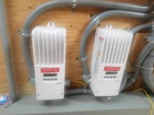
As I have mentioned before I have configured my Trace inverter operate in Low Battery Xfer mode, where the system runs off of battery until the battery drops to 19.2 volts. At that point, the LBX, the inverter reconnects to the grid, where it powers all the loads and charges the battery

The LBCIN (Low Battery Cut IN) is programmable, and I had had it set at 24.9 volts. It would run some 5 to 6 hours doing that until the battery was full. Usually the LBX occurs in the early morning hours of the next day after a cloudy day previously. If the new day has a sunny non-cloudy day, most of that sun is wasted since the battery was filled by the grid

A friend noticed and suggested I reprogram the LBCIN to say 22.5 volts and use the grid for a partial battery charge, enough to sustain the house loads until the sun comes up and then use the sun to charge the battery to full. After looking at the daily charge charts I see this might be the best way operate - given that sunny days will occur more often here.

So the expectation is that instead of 5-6 hours of grid charging the battery to full, that 2 to 2.5 hours of partial charging will be sufficient to allow the house loads to operate until the sun can fully charge up the battery

If the next day is not sunny, well the grid will be reconnected to and restart the charging process again

here are files of Sept 9th when the grid connected (at 1AM) and charged the battery full (at 7AM) and the next day the solar energy was wasted because the battery was full

and Sept 13th where the sun recharged the battery to full after a night where the battery supplied the energy without having to grid connect

With the new policy, the charging of the battery will stop when the battery reaches 22.5v which, on the 9th, occurred after 3AM. Thus lasting just over 2 hours. That will save 4 hours of buying grid energy. Again this will operate if the new day has full sun. If clouds occur, the grid connection sequence will repeat

I have found that my Trace inverter is unique in allowing me to set the LBX and LBCIN points, while other inverters today are pre-programmed and not changeable.
 

Attachments

  • 2020-09-09.pdf
    1.9 MB · Views: 6
  • 2020-09-13.pdf
    1.9 MB · Views: 8
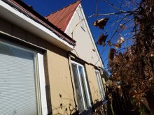
Well I finished up the hard part of putting up siding on my southeast A gable of the house. Now I am back on finishing solar panel installs

first pics of the new siding - much better than the flaking paint, lower portion I can paint without the scaffolding, as well as do trim up work on edges and windows

20201021_143449.jpg

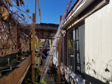
moved the scaffolding west under the solar panels

20201021_143455.jpg

20201021_143512.jpg

now the rewire and rearranging of array 2

I removed column 1 (left) of itspanels, then moved 2 rows of column 2 (top panel pictured) into column 1, and rewired from 24v to 48v configuration

20201021_121225.jpg

below column 1 waiting for its last top panel to be moved over into position
Array 1 seen over edge of roofline on outbuilding

20201021_121236.jpg

Once I get this rewired and the 6 310w panels positioned here in array 2, I will then install the 6 panels (355w) onto array 3 (pictures posted earlier)

Trying to get these all up before it gets cold/wet/dangerous
 
this morning moved the top panel from col 2 to col 1 and then bolted all 3 panels down nice and tight


20201022_133007.jpg

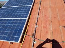
tied down the wiring and put wires in a 2" conduit until they are under the panels
thinking about again using some conduit, notched out to cover the cross wires and mount the conduit to roof ridges
the requirement is to keep the wires OFF of the roof to stop wire insulation wear by wire movement

20201022_133015.jpg

and 2 panels patiently waiting now to be remounted

20201022_133216.jpg

took about 1.5 hours to position, wire and tie, all safely
 
Thanks for keeping this awesome thread updated @dougbert. It’s good to see you are finally living the off-grid dream after all these years!

I wanted to ask whether you’ve explored the possible benefits of reducing your consumption by running DC wiring within the house and running devices which commonly use AC “wall wart” power adapters directly from DC (with appropriate DC/DC voltage conversion as needed)? Unless I misunderstood, your approach until now seems to be to convert your DC via an inverter and continue running all the house via AC. I may of course be wrong in that assumption, so sorry if I didn’t read your posts thoroughly enough.

After all, consumption watts saved are just as valuable as extra watts generated through adding ever more solar panels.

thank you for the comment - Ha det bra! in Sverige

I spent a couple of years in Norway back in 1975-1976
Many of my logins on computer systems are 'norsk5'

Yes, with the cheap DC panels now (compared to 20 years ago) I do run the whole house on AC. It is easier today. 20 years ago I thought about a set of DC circuits to a new DC frig and DC freezer, but they were expensive then (and still are).

With cheaper PV, I am capable of use excess PV to heat water as a pre-heater to my gas tankless water heater.

So yes, I will continue to generate DC, store in the battery and convert to AC to run the house

I do have a small 12 DC system only that runs my HAM radio shack. I recently upgraded the controller from a 20 amp Morningstar to Will's recommendation of EPEVER 40 amp controller. My almost dead set of 2 golf cart batteries will shortly be upgraded to 200amp-hr of LiFePo batteries - ?

I do have several radios being charged on AC at the moment and I do have DC to DC regulators I am going to use to convert to charging off of the HAM system instead of the house AC system. Possibly more wall warts might be done
 
Last edited:
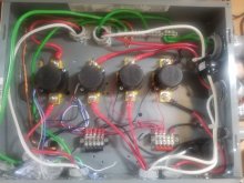
yesterday a friend came over (I asked him to do so) and he helped me install the lonely 2 panels plus their cousin that was on the ground
so array 2 is done! rewired to 48v configuration and 6 panels (3 circuits setup) 310 watts each

took 2 hours to do all 3 panels
the scaffold is great doing this
now I have to move the scaffolding under array 3.
rain and snow coming next saturday evening
GOT TO GET panels up on array 3 this week - anyone game to come help - just kidding

1860 watts max possible - yeah right

at this moment they are generating (in bright sun as seen in the picture I just took at noon) 1540watts with 59.9 amps @ 24.14 volts on the battery side of the controller. The controller has a max of 60 amps then starts throwing EVENT codes of OVER CURRENT. I might have to disconnect the breaker on one of the 3 circuits. But on cloudy days I should be able to turn them all on without worry


20201101_112902.jpg

pic again of array 2, with the open field for 6 panels in array 3 on the right

20201101_112905.jpg

below is array 1:
4 310watt NEA panels
4 100w 20 year old panels

(2 100w panels on the right are the HAM radio panels - not part of array 1)


array 1 is generating
1343 watts with 52.6 amps of current right now

20201101_113103.jpg

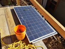
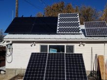
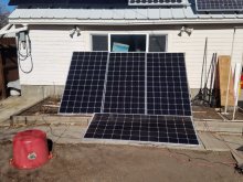
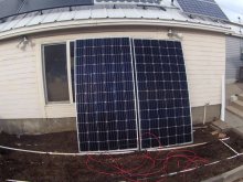
below is array 3 currently residing in our small corn patch on the ground
these plus 2 more panels are going on the roof in the array 3 area

array 3 is generating 1030 watts with 42 amps of current right now


20201101_113117.jpg

and 2 more panels going up in array 3 area


20201101_113132.jpg

total wattage production from all of the above is 3.7kw right now at noon MST
I figure around 4500 watts installed
temp is 55F at altitude of 5535ft
the sun is currently at 35 degrees above the horizon

BTW: I even washed (Windex 2nd story spray bottle at end of hose) all the panels last evening - they WERE dirty, especially the ones laying down or on the ground

dougbert
 
Last edited:
I tried hard, but failed, to get any panels on the roof by last saturday when the winter storm hit
I ended up at the ER for a blood infection like I have had previously and that blew my weekend.
Since then we have had cold temp, ice and snow, so I stayed off the roof, waiting for better temps next week

So I came inside and worked on the wiring for Array #4 and its charge controller to the outside:

here is the fully wired controller on the left.

Charge controllers for Arrays 3 and 4.jpg

downstream output wire goes over to the 80amp breaker and then to the common positive busbar near the batteries

upstream wires comes from the Incoming Contactor box below

Array 1-4 Contactor box.jpg

contactor #4 for array #4 is on the right and wired up to the incoming wires.
Those incoming wires go into the crawl space on the way to the west where the combiner box will be located on the outside west wall

Disconnecting combiner box Midnite Solar.jpg

Next will be to drill a 1" penetrating hole for the conduit and mount the combiner on the current siding (new siding coming next year)
 
at this moment they are generating (in bright sun as seen in the picture I just took at noon) 1540watts with 59.9 amps @ 24.14 volts on the battery side of the controller. The controller has a max of 60 amps then starts throwing EVENT codes of OVER CURRENT. I might have to disconnect the breaker on one of the 3 circuits. But on cloudy days I should be able to turn them all on without worry

Parallel strings? Add some standoffs so they have different angles, present less total area to the sun. That will reduce peak current. But you'll get more hours of decent current.
 
Parallel strings? Add some standoffs so they have different angles, present less total area to the sun. That will reduce peak current. But you'll get more hours of decent current.

the real solution is to buy my intended 48v inverter (15kw) and convert my battery to 48 volt and over current goes away

My plans include 4 arrays, east, south and west, just not there yet

array 1 will have 6 panels to the south and 4 panels to the west
array 2 will have 4 panels south on the roof with 2 panels on the side wall on the south
array 3 will have 4 panels to the south and 4 panels to the east\
array 4 will have 10 panels to the west on a pegola and deck

I estimate a spec of 12kw of panels

dougbert
 
Your list of "arrays" has multiple orientations per array, and different numbers of panels for each.
At first glance, looks like it needs 7 charge controllers.

Will this use your existing SCC, or need additional ones?
Each different length string (or different Voc of string) has to be on a separate MPPT.
But you can parallel different orientations of the same length.
I would try to make several long strings, each out of panels with a given orientation.
Then parallel some of same length different orientation, so each SCC works more hours.
Of course you have a variety of panels, different amperages, so each needs its own string.


each of my arrays feed into a combiner box which feeds into that array's SCC.
The individual strings that feed to the combiner box are 2 24 volt panels for a nominal of 48 volts per string. Both panels of each string are oriented in the same direction.

Currently, all facing south

array 1 has 3 strings - 1400 watts
array 2 has 3 strings - 1700 watts
array 3 has 3 strings - 1700 watts

in the future after the new 48 volt inverters I will add

array 1 will have 2 more strings - 1400 watts facing west
array 3 will have 2 more strings - 1200 watts facing east
array 4 will have 5 strings - 3000 watts facing UP on top of the new pegola over the new deck
 
had great weather today, 47 F high around 2PM when I began the final work on array 3
I installed the final 3 panels of array 3

So I will have 6 panels on array 2 and 6 panels on array 3 for now.
Later with the new 48v inverter, array 2 will have 8 panels
while array 3 will have 4, with room for 4 more later on the east roof slope

Finished the work just after sunset and dusk, as I clean up the tools, etc so no pictures tonight

tomorrow I will take pics and measure voltages and other sanity checks and then turn things on
BIG milestone finished today, as it will be in the lower 40s this next week with possible rain/snow forecast

I might be able to add 2 panels to the west facing roof slope in the coming days (next friday/saturday might be clear) and tie them
for the short term into the SCC that will be used for the future array 4.
After the new 48v inverters, these panels will be tied to array 1's combiner box, but for now will use array 4's combiner
Then next spring will add 2 more panels on the west facing roof slope - might be able to make it over the next couple of weeks if
we get good weather

dougbert
 
got sun today so captured some pictures of arrays 2 and 3

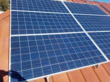
array 2 on the left (blue) and 3 panels of array 3 (black) on the rigth. Both sets are 72 cell panels

array 2 A.JPG

6 panels of array 3

arrary 3 A.JPG

again array 3

array 3 B.JPG

looking NE over array 3. Got those last 3 up by myself, rope and some effort. So glad that it is DONE

array 3 C.JPG

I moved 2 panels from this, our "corn patch" of the garden to the roof, leaving behind 2 panels that are currently not attached
but will move them to the west facing roof of the house, last picture


Left in Corn Patch.JPG

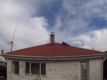
west facing roof (Notice old flaking paint, most of outside covering of this 90 year old house had that failing paint, but all of the old walls are being covered by the new insulated siding of prior pictures). And yes the old chimney needs some attention as the mortar fails

There will be a new deck built on this side of the house as well, covered by a pegola and array 4 on top of that.

plans and more plans, slowing being put into reality.
This Old House is 24 ft wide by 48 ft long, Bungalow is how I have heard it called.

I figure I can put 4 total panels on that roof area, 2 in the center and 1 each on the left and the right


array 4 location.JPG
 
Last edited:
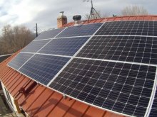
last saturday I was able to wire up the combiner box and feed wire from that combiner box back to the contactor for Array 4

all except for the butt splice in the crawl space as I was still awaiting 2 splices from amazon. Those arrived yesterday (Monday) morning and I spliced the 2 segments together. Once all was connected I attached the 2 remaining panels in the "corn patch" and verified good correct voltage all the way back to the controller and I flipped the switch/breaker ON.

the controller registered 520 watts after a short connection period. 2 panels, 355 watts each for 710watts max.
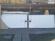
I will watch for higher generation. I am also repositioning the panels to be mounted on the wall off of the ground, as snow plies up there.

Next step is to finish modifying the last 4 panels by adding new PV leads with MC4 connectors.
2 panels will be temporally mounted on the above wall facing west. I have on order a 12" drill bit 1/4" that I will use to drill mounting holes for the 2 rails going on the roof, when those are installed, the last 2 panels will be placed on those rails

Currently actual solar production has reached 4.6. Maybe a bit more, will watch that. Then adding the 4 other panels might get us to 5.5kw of production

I thought about a picture of the crawl space, but naw, it is joists, dirt, conduits, water pipes, etc. Nothing special
I will take a picture of the disconnector/combiner box combo and associated conduit. That conduit will be covered over with OSB and siding panels

Note on the chimney: Wife wants me to take it down entirely, so next spring that will happen and the hole covered
 

diy solar

diy solar
Back
Top