diy solar

diy solar

New Daly "Smart" BMS w/ Communication. (80-250A)

Hallo,

This below is what I have done:

I have a DeliGreen (Daly) 8S 24V Smart BMS, and as always there is only 1 (one) UART port, either for Bluetooth connection (Smartphone application) or for USB serial cable connection (PC application). But, I want to monitor the BMS both wirelessly; using Bluetooth (Smartphone application = SmartBMS), and also wirelessly using WiFi/Internet for PC application (PCMaster).

First step, I built the TTL/UART -to- WiFi Bridge, (Serial -to- TCP/IP). I do not use Raspberry nor Arduino, but there must be a device that works as the TCP Server, here I use ESP8266 module, with the JeeLabs ESP-Link firmware installed. After this setup done, I will have the serial data coming from the BMS, available in the format of TCP/IP, which can be accessed on my WiFi network. Then on my PC, I created a Virtual COM Port, set according to the IP & Port address of the WiFi Bridge. DONE…..!!! At this stage I can monitor the BMS wirelessly via WiFi from my PC, using the PCMaster application. Technically, if I share this port, I can then monitor the BMS via internet, anywhere in this world, (as long as internet is available).

I did not stop here, when I am not working on my PC and just with my smartphone on my hand, and not far away from the BMS (in the Bluetooth signal range), I also want to monitor the BMS via Bluetooth…. So, I also want to connect the Bluetooth dongle to the BMS UART port… BUT, the port has been occupied by the WiFi Bridge…. So, I need to combine this 2 ports from WiFi Bridge and from Bluetooth dongle, to be connected into 1 port of the BMS UART port.

Second step, I built a port combiner, the task of this combiner is to combine the Tx from WiFi Bridge and Tx from Bluetooth dongle, into a single Tx going to the BMS Rx. While the Tx from the BMS can be shared to the Rx of WiFi Bridge and Rx of the Bluetooth dongle. I built this combiner using 3 NOR Gates of the Quad NOR Gate IC, CD4001. DONE….!!! At this stage I can monitor the BMS wirelessly via WiFi and via Bluetooth…

Still, I do not stop here, now I am decoding the serial data coming from the BMS, and will integrate them into my Node-RED, and this will be presented on the same User Interface as my other IoT stuff running now on the Node-RED… So, I only need to open the Node-RED user interface, and I can monitor & control all my IoT devices, including this BMS, anywhere in this world (again, as long as internet is available).

Attached some pictures of my simple hardware, only has 3 main components, (ESP8266, CD4001, and DC-DC Converter)… Sorry for the quick, dirty and ugly of my hand scratch of the diagram, but you can grab the idea from that….

Regards,

Antonius
Sorry for the noob questions ... what is the purpose of the CD4001 you use? Is it necessary?

Is there any way, even just for monitoring the system/BMS to connect the UART to an ESP device using your system?

I am hoping to monitor it with Home Assistant.
 
Hi,
The CD4001 (NOR Gates) is used to build the "combiner", it is necessary if we want to combine the signals from WiFi Bridge (ESP) and Bluetooth dongle.

It is possible to monitor the BMS using the ESP.
 
Hi,
The CD4001 (NOR Gates) is used to build the "combiner", it is necessary if we want to combine the signals from WiFi Bridge (ESP) and Bluetooth dongle.

It is possible to monitor the BMS using the ESP.
Thank you for the quick reply.

I do know that HA does have the Node-Red add-on, I am wondering if setting up the ESP bridge, using JeeLabs ESP-Link firmware, connecting to the BMS (without the CD4001 and ignoring BT) and then running Node-Red through my Home Assistant, utilizing your Node-Red txt file will work?

I am not a coder or electronics guy by trade but am pretty good with it nonetheless this is slightly above my pay grade so I greatly appreciate any insight/help you can give.

Does this work with ESP32 as well as the ESP8266?
 
Hi,
If a serial port combiner is not needed, then CD4001 is not necessary, this means the 1x BMS UART port will only be connected to 1x device (the ESP only), the Bluetooth dongle is not used. Basically the ESP Bridge (ESP8266/ESP32) is to replace the physical UART cable, means that we can connect the BMS wirelessly/remotely (via WiFi, instead of via Bluetooth), no need cable, and using WiFi give us possibility to access it via Internet.

I use ESP8266, but ESP32 should do the same, just some drivers might be different.

I do not use HA, all my IoT devices are controlled via Node-Red....
 
Hi, just saw this post, regarding those 3pins in the middle on your picture, mine is exactly like that, and i connect the usb cable from the package to that port to program the BMS with PC! so i doubt it has anything to do with relay, because it works with both Daly PC apps, simultaneously with BT being connected to the other side. Mine is R05A-GC18 (4S 12V 100A) and the 3pin is labeled monitor.
Ok thanks! Sorry to reply to you a year late, but I only just saw this. :giggle: Good to know what that connector is for. Mine is 4S 80a model so I am sure it will be the same as your 100A one.
 
if anyone interested, i have build a little program for the ESP8266 (wemos D1 mini) to get the Daly BMS values into a web interface and send it over MQTT, it is possible to switch the MOS Gates for charge and discharge and get varius data
Great work. I will test it with HA.
Btw, has anybody succeeded to emulate this BMS as a supported battery (like pylontech)? Essentially I would like to connect it to a Easun SV4 (CAN, RS 485 or RS 232)
 
Hello everyone
I'm using a Daly smart BMS with a logger created by Nuno Faria, (https://github.com/njfaria/dalylog) connected by RS485 to USB cable, and connected to Solpiplog by the same creator.
The software runs on a raspberry pi 4
View attachment 25641
View attachment 25642
Hi! I am trying to connect my dalybms to my piplogger. for some reason the MQTT wont connect, any hints on what i am doing wrong? should i put some kind of info into the piplogger program as well (username,pw?) i have tried the same "IP" on both, i keep the port to 1883. the only thing is that localhost can't be changed in the daly program, on my piplogger i must type emoncms.org for it to send any data there, maybe this is the problem? or maybe i need to do something else
 
What is the reconnect behaviour of the Daly smart BMS after a high or low voltage cut off event? Does it reconnect automatically or is it only when the user goes into the app and reenables charging or discharging FET that the connection is made again?

I guess on high voltage event it is only the charging FET which switches off, and vice versa (discharge FET) for low voltage cutout?
I does resume charging/discharging on its own.
 
A couple more Qs to confirm what I think I know.

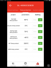
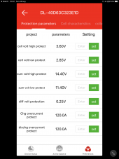
In the attached screenshots the ”charge over current protect” and “discharge over current protect” are set to 120A, which should be the default setting as I don’t remember changing these. But this was sold as an 80A BMS, so should I be adjusting these down to 80A to ensure my FETs don’t go pop? Or is it normal that Daly BMSs have these set to 150% of the notional rated current?

Second Q - the charge and discharge high temp protect settings are 65C and 70C. Do these refer to the temp of the BMS or the temp seen by the NTC thermistor (battery temp)? If so, aren’t they pretty high? I don’t think I want to be charging my battery when it’s over 50C so might adjust this down.

709AE232-C267-4AC7-8C2B-B213F2745946.pngF333E932-3A2E-4CC3-B436-CDEAA41D180C.png
 
Hi,

Q1- if the Daly BMS was sold as an 80A unit, I would for sure set max charge and max discharge no higher than 80.

More importantly, what are the ratings of your battery? What your battery’s are rated at will give your your ‘C’ rating, 1C being 1 x C. If your battery has a rating of 100A, 1C would be 100, 0.5C would be 50, and so on. Check battery specs and you will normally see maximum charge/discharge levels expressed as a C rating. If you keep to maximum discharge/charge C levels, you will affect long term performance, keeping under these (say charging at no more that 0.5 C) will help cycle life greatly. Again, look at cycle life charts for you batteries, a small setting can make the difference between 4000 cycles or 8000 cycles, double battery life!).

Q2. NTC temp sensor is plugged into Daly and pushed into the middle of your battery back (to get good thermal contact in your cell pack). When charging/discharging any temps over 50C are going to have an adverse affect on cell life. Cell temps are normally higher when you charge/discharge closer to 1C.

Lots of the settings within the Daly app are maximum settings for the daly to protect against (going under/over). You are still expected to use external components to keep these settings within range. For instance, an 80a daly can be set for 1C charge rate (80A), your charge controller can then be set for max 70A output (giving your 10A protection window). If you go over the ratings of the daly it will complain and cut out (leaving you in darkness, etc.).

Make sure to use a decent (Class T are best, a must really) fuse on the load connected to the daly, this should be rated at no more than the dalys/batteries (which ever is lower) maximum rating. As a rule of thumb, keep fuses as close to your battery pack as possible, that way you won’t get unfused high current cable runs.

While you are at it, within the Daly app, check your max cell voltage/max pack voltage settings. Max cell voltage x the number of cells you have gives you max pack voltage.

I have had 4x LifePo4 packs running for 15 months now. Each pack is a 200A Daly with 16 105A LifePo4 cells. They run my house full time. Keep well with the limits you set on the Daly and once fitted, you can forget…

Dan
Thanks for answering my questions Dan. I’ve set the temp protections to 50C and also adjusted down the over current settings. Puzzling why an 80A bms comes with 120A set as the current limits, but maybe this is intended to allow for brief surge currents and the MOS temp limit is the one which cuts the power if the BMS is getting too stressed.
 
Thanks for answering my questions Dan. I’ve set the temp protections to 50C and also adjusted down the over current settings. Puzzling why an 80A bms comes with 120A set as the current limits, but maybe this is intended to allow for brief surge currents and the MOS temp limit is the one which cuts the power if the BMS is getting too stressed.
I would advise you to drop the temp protection settings lower. all data indicates that liFePo4 batteries life cycles are severely shortened by high temps and by over low temps. most folks got for 5C-35C . and then they build subsystems or create a climate in one form or another to avoid them so that the BMS is the failsafe... not the daily workhorse.

I am currently using four of the 16s 150/200 DALY units for my 48 volt packs. remember when using mosfet based BMS that you should honestly derate them a bit for longevity purposes. mine rarely see more than 30/40. that 30 charge, 40 discharge. it is the nature of the beast. any of the rest of them (JBD, etc, et al) all have the same basic limitations though the DALY with its larger heatsink and in the case of the 12/24 volt high power units a fan are a little more robust in that area. you will notice a lot of folks who speak badly of them but have never used them. Realize that their are people on this forum with a vested interest in selling certain products, regardless of if they are a "vendor" or not.

Is set my SCC to the volts I want as well as the max charge rate, same for my inverter. I use a combination of passive and active heat control to keep the batteries in the zone. it has worked well so far. I am not a vendor, nor am I a big video or photo person, though if you need a pic or two to help given time I can.
sorry to clarify... 5C up to 35C not -35C.
 
I would advise you to drop the temp protection settings lower. all data indicates that liFePo4 batteries life cycles are severely shortened by high temps and by over low temps. most folks got for 5C-35C . and then they build subsystems or create a climate in one form or another to avoid them so that the BMS is the failsafe... not the daily workhorse.

I am currently using four of the 16s 150/200 DALY units for my 48 volt packs. remember when using mosfet based BMS that you should honestly derate them a bit for longevity purposes. mine rarely see more than 30/40. that 30 charge, 40 discharge. it is the nature of the beast. any of the rest of them (JBD, etc, et al) all have the same basic limitations though the DALY with its larger heatsink and in the case of the 12/24 volt high power units a fan are a little more robust in that area. you will notice a lot of folks who speak badly of them but have never used them. Realize that their are people on this forum with a vested interest in selling certain products, regardless of if they are a "vendor" or not.

Is set my SCC to the volts I want as well as the max charge rate, same for my inverter. I use a combination of passive and active heat control to keep the batteries in the zone. it has worked well so far. I am not a vendor, nor am I a big video or photo person, though if you need a pic or two to help given time I can.
Thanks Ken - I do agree with your cautious approach and I’d actually be amazed and worried if my battery ever got close to 50C, so probably I should set that limit lower.

I know some people have to house their batteries in small, hot compartments in yachts or vehicles but mine lives in a room of my house which is rarely above 25C ambient except in mid summer which it could be 3-4C more than that. I guess what I’m saying is that unless my battery is seeing discharge currents far higher than I’m planning, it should not be getting hot anyway. (y)
 
Puzzling why an 80A bms comes with 120A set as the current limits, but maybe this is intended to allow for brief surge currents and the MOS temp limit is the one which cuts the power if the BMS is getting too stressed.

I'm pretty sure all/most of Daly Smart BMS units come with the same defaults - for my 250amp unit I had to raise those numbers from 120 to 125 (charge) and 250 discharge.

@Dforster @ken morgan - it sounds like you guys both have multiple packs, each with their own Daly BMS, paralleled together? I heard problems with paralleling multiple daly bms units UNLESS you pay more for their BMS with parallel units, but I'm very curious to hear if this is just marketing BS from those who actually have 3 or 4 units in parallel together. Let me know, thanks!
 
So in answer to my settings:-

READ THE BATTERY SPECS! Buy what you need for your application, there is no magic 'one fits all' solution.

1. Bat Temp:
I live in the Caribbean, which sounds nice, and it is, but we get lots of sun, hot sun, the ambient daytime temp is 32C/humidity 75% plus. If I set my BMS (Daly) max temp settings to 35C, it would cut out all 4 batteries by midday, and when they cut out, the batteries remove all power from my solar inverter system (14kW solar / 12kW stacked x4 VFXR3048E Outback Inverters - stacked, 4x FM80 80A MPTT chargers) leaving the house in blackout. Its impossible to achieve those low temps, ideal yes, but not achievable for me. So in my case, I brought batteries rated to 60C MAX charge/discharge, and go no further than 50C to keep on the safe side. Bear in mind these are the same specs that I (any many) chose to read my 1C rating, etc. from. I don't 'cherry pick', what the specs say I stick too, (under to be on the safe side).

2. Daly App.
Don't go over your max battery/bms (whichever is lower) current rating, its a road to batteries that look like they have had to much KFC (they get fat and die quick).
I'm pretty sure all/most of Daly Smart BMS units come with the same defaults - for my 250amp unit I had to raise those numbers from 120 to 125 (charge) and 250 discharge.

@Dforster @ken morgan - it sounds like you guys both have multiple packs, each with their own Daly BMS, paralleled together? I heard problems with paralleling multiple daly bms units UNLESS you pay more for their BMS with parallel units, but I'm very curious to hear if this is just marketing BS from those who actually have 3 or 4 units in parallel together. Let me know, thanks!
…so the secret to running parallel BMS units is easy. Set your external devices (loads/chargers) to just under the ratings for one of the battery packs. That way, if (in my case), 3 of my 4 packs go into error (very unlikely) the charge/discharge current values are still good for the remaining single pack. Surprisingly, all packs have kept in sync 99% of the time. If one pack does cutout, I am careful to make sure an alarm informs me so I can get it back online quickly- so I don’t have to do a rebalance. Maybe it’s happened twice in 15 months (and thats because I charged at too higher voltage during some experimentation).

The biggest thing that keeps the Daly/lifepo4’s happy is keeping well within any top/bottom values you set. Work to battery limits and expect a few blackouts…
 
Back
Top