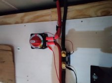
I have been trying to figure out how to add a sub panel upstairs but not seen any way to do so due to the n/g requirement. I may just have to live with a 240v only panel.Yes. The cargo trailer will be connected to a main panel in the post barn that will be grounded and have a neutral / ground bond
You are using an out of date browser. It may not display this or other websites correctly.
You should upgrade or use an alternative browser.
You should upgrade or use an alternative browser.
Off Grid Farm ~ Mobile Power Cargo Trailer Build: Growatt 12kw Install
- Thread starter MrM1
- Start date
MrM1
I'm Here, But I'm Not All There
Not sure what you are saying. Is there a N/G bond issue with this growatt inverter?I have been trying to figure out how to add a sub panel upstairs but not seen any way to do so due to the n/g requirement. I may just have to live with a 240v only panel.
MrM1
I'm Here, But I'm Not All There
I did just tested the inverter. I do not have an N/G bond in my panel yet (that will happen at the main panel, the one in the trailer is a sub).I have been trying to figure out how to add a sub panel upstairs but not seen any way to do so due to the n/g requirement. I may just have to live with a 240v only panel.
But I did test the inverter powered off. There IS a bond between the Case ground and the Busbar Terminal Ground input.
BUT ... There is NO N/G bond between the Ground input and the Neutral output. And There is No N/G bond between the Case ground and the Neutral output.
So unless there is some kind of internal transfer switch that is closed when powered up and in Inverter mode ... there is NO internal N/G bond in the Growatt 12T that I can see.
What has been others experience??
Without the n/g and you put a 120v load it will not track, one leg will be at 140v the other at 90v give or take.I did just tested the inverter. I do not have an N/G bond in my panel yet (that will happen at the main panel, the one in the trailer is a sub).
But I did test the inverter powered off. There IS a bond between the Case ground and the Busbar Terminal Ground input.
BUT ... There is NO N/G bond between the Ground input and the Neutral output. And There is No N/G bond between the Case ground and the Neutral output.
So unless there is some kind of internal transfer switch that is closed when powered up and in Inverter mode ... there is NO internal N/G bond in the Growatt 12T that I can see.
What has been others experience??
MrM1
I'm Here, But I'm Not All There
So are you saying needs to be bonded in the panel BECAUSE it's not bonded in the Inverter?Without the n/g and you put a 120v load it will not track, one leg will be at 140v the other at 90v give or take.
Is this a fault/problem of the inverter, or is this a panel wiring thing? Is that why you can not use this inverter?
I would like to add a sub panel and have researched doing so. But I have seen an answer for the n/g bond. Without th n/g both legs diverge on voltage greatly.So are you saying needs to be bonded in the panel BECAUSE it's not bonded in the Inverter?
Is this a fault/problem of the inverter, or is this a panel wiring thing? Is that why you can not use this inverter?
MrM1
I'm Here, But I'm Not All There
OK Part 1 of the Off Grid Farm Cargo Trailer build and install is up. The audio is not as loud as it should be, but it's OK.
MrM1
I'm Here, But I'm Not All There
12 kw Cargo Trailer Install coming out nicely. Mostly done. All DC connections done, all In-Trailer AC done. All solar connectionless points via Anderson Connectors done. Just clean up., labels, and programing left. Then it's off to the farm to connect it all to the main sub panel and solar panels.
MAIN AC OUT / SOLAR IN PASS THROUGH
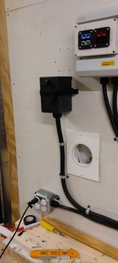
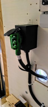
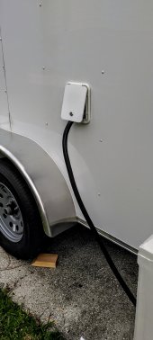
SOLAR INPUT BOX
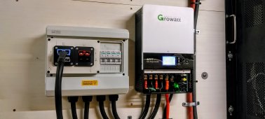
FULL POWER WALL
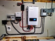
AC AND DC CONNECTIONS, In trailer receptacles lights and switches
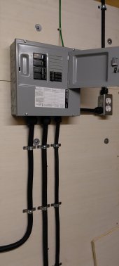
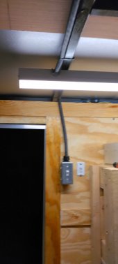
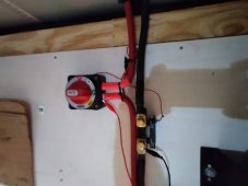
MAIN AC OUT / SOLAR IN PASS THROUGH


SOLAR INPUT BOX

FULL POWER WALL

AC AND DC CONNECTIONS, In trailer receptacles lights and switches


SniperX
Solar Enthusiast
- Joined
- Apr 1, 2021
- Messages
- 345
Coming in very late to the party, but I like your system setup. Wondered if you might help me out with a few questions I have? I have the same hybrid inverter and the same mppt controller. I am trying to figure out a system and I just don't understand it enough to know what to do. I am reading and reading and I came across your thread.
First of all, I LOVE that you used Anderson connectors. I bought an Australian-made camper, and that was the first time I had heard of those. Did you get those on Amazon or from another source? What amperage rating do they have?
Second- Did you use the secondary MPPT to supplement the 12kw Growatt in the sense that you wanted more solar for cloudy days? I can't tell by the wiring but do you have solar going directly to the 12kw and then solar going from the mppt to the growatt 12kw? This is where I am getting a little confused. Someone suggest I purchase the extra MPPT but I don't know if it is supposed to go straight to the batteries or go into the 12kw?
Third- on your sub-panel, it gets out of focus to blow it up, but on the left side, is that TWO 60 double poled circuit breakers and on the right you just have two 20As and a 15A? The 60A goes to the RV plug (green handled cord) but does the other 60A go to wall outlet plugs (assuming all four are 15A plug-ins?
I can't see the video you posted on this page, otherwise, I would watch that and probably get all my answers. It just shows a black box with no link.
I think your setup is the solution to my problem if I can just get those questions answered. I purchased 12 acres in Suwannee County and need a portable setup.
MrM1
I'm Here, But I'm Not All There
Thanks
The Andersons I bought direct from Powerwerx. I have seen stories of the ones on Amazon being fakes or knockoffs.
I bought the 2nd SCC because the Growatt 12k Inverter AIO is rated for a 7000 watt array (3500 on PV1 and 3500 on PV2) And we have a total of 11,800 watts. You can over panel the Growatt a little (maybe) , but not that much. So to not waste the extra power and risk melting something down we got the 2nd SCC.
This will be the basic idea of our final wiring (most of it is completed now in the t railer). Solar will be out on the roof of the barn and I will build up another Anderson connector box to mount on the pole. I am using 10 awg from panels to combiner, and 8 awg from combiners to SCCs
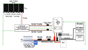
On the sub panel (which is functioning as the main panel where Neutral and Ground are bonded), One 60 amp breaker is the main in from the Growatt, The other 60 amp is Main power out that will go to a larger distribution Sub Panel mounter perminantly at the farm. This will connect via teh 60 amp 6 awg generator cable. This panel will feed the whole farm.
The 15 amp and Two 20 amp breakers feed the light and recepticle next to the panel (15 amp) and each 20 amp feeds 1 recpticle in the double recpticle box. One on L1 and one on L2 to help keep loads balanced at the inverter.
Have no idea why you cant see the video. It is just a typical youtube video. Can you see other videos on youtube? I do not make my videos for kids so if you have somekind of youtube parental controls that might be why
The Andersons I bought direct from Powerwerx. I have seen stories of the ones on Amazon being fakes or knockoffs.
I bought the 2nd SCC because the Growatt 12k Inverter AIO is rated for a 7000 watt array (3500 on PV1 and 3500 on PV2) And we have a total of 11,800 watts. You can over panel the Growatt a little (maybe) , but not that much. So to not waste the extra power and risk melting something down we got the 2nd SCC.
This will be the basic idea of our final wiring (most of it is completed now in the t railer). Solar will be out on the roof of the barn and I will build up another Anderson connector box to mount on the pole. I am using 10 awg from panels to combiner, and 8 awg from combiners to SCCs

On the sub panel (which is functioning as the main panel where Neutral and Ground are bonded), One 60 amp breaker is the main in from the Growatt, The other 60 amp is Main power out that will go to a larger distribution Sub Panel mounter perminantly at the farm. This will connect via teh 60 amp 6 awg generator cable. This panel will feed the whole farm.
The 15 amp and Two 20 amp breakers feed the light and recepticle next to the panel (15 amp) and each 20 amp feeds 1 recpticle in the double recpticle box. One on L1 and one on L2 to help keep loads balanced at the inverter.
Have no idea why you cant see the video. It is just a typical youtube video. Can you see other videos on youtube? I do not make my videos for kids so if you have somekind of youtube parental controls that might be why
SniperX
Solar Enthusiast
- Joined
- Apr 1, 2021
- Messages
- 345
So you decided against the 6awg for the PV wiring? Was it too big for the terminals?Thanks
The Andersons I bought direct from Powerwerx. I have seen stories of the ones on Amazon being fakes or knockoffs.
I bought the 2nd SCC because the Growatt 12k Inverter AIO is rated for a 7000 watt array (3500 on PV1 and 3500 on PV2) And we have a total of 11,800 watts. You can over panel the Growatt a little (maybe) , but not that much. So to not waste the extra power and risk melting something down we got the 2nd SCC.
This will be the basic idea of our final wiring (most of it is completed now in the t railer). Solar will be out on the roof of the barn and I will build up another Anderson connector box to mount on the pole. I am using 10 awg from panels to combiner, and 8 awg from combiners to SCCs
View attachment 116406
On the sub panel (which is functioning as the main panel where Neutral and Ground are bonded), One 60 amp breaker is the main in from the Growatt, The other 60 amp is Main power out that will go to a larger distribution Sub Panel mounter perminantly at the farm. This will connect via teh 60 amp 6 awg generator cable. This panel will feed the whole farm.
The 15 amp and Two 20 amp breakers feed the light and recepticle next to the panel (15 amp) and each 20 amp feeds 1 recpticle in the double recpticle box. One on L1 and one on L2 to help keep loads balanced at the inverter.
Have no idea why you cant see the video. It is just a typical youtube video. Can you see other videos on youtube? I do not make my videos for kids so if you have somekind of youtube parental controls that might be why
Last edited:
SniperX
Solar Enthusiast
- Joined
- Apr 1, 2021
- Messages
- 345
Just got back from researching the amazon Anderson plugs and decided against the all since they are knock-offs and came back here to find your response. Thanks for the tip for powerwerks!Thanks
The Andersons I bought direct from Powerwerx. I have seen stories of the ones on Amazon being fakes or knockoffs.
I bought the 2nd SCC because the Growatt 12k Inverter AIO is rated for a 7000 watt array (3500 on PV1 and 3500 on PV2) And we have a total of 11,800 watts. You can over panel the Growatt a little (maybe) , but not that much. So to not waste the extra power and risk melting something down we got the 2nd SCC.
This will be the basic idea of our final wiring (most of it is completed now in the t railer). Solar will be out on the roof of the barn and I will build up another Anderson connector box to mount on the pole. I am using 10 awg from panels to combiner, and 8 awg from combiners to SCCs
View attachment 116406
On the sub panel (which is functioning as the main panel where Neutral and Ground are bonded), One 60 amp breaker is the main in from the Growatt, The other 60 amp is Main power out that will go to a larger distribution Sub Panel mounter perminantly at the farm. This will connect via teh 60 amp 6 awg generator cable. This panel will feed the whole farm.
The 15 amp and Two 20 amp breakers feed the light and recepticle next to the panel (15 amp) and each 20 amp feeds 1 recpticle in the double recpticle box. One on L1 and one on L2 to help keep loads balanced at the inverter.
Have no idea why you cant see the video. It is just a typical youtube video. Can you see other videos on youtube? I do not make my videos for kids so if you have somekind of youtube parental controls that might be why
Weird, the box was black and then all of a sudden, coming back I see the video. I went to your channel and subscribed and liked the video. Now, I come back and can see it. I appreciate the diagram.
So 4/0 from batteries to the busbar and then did you use 2 AWG from the busbar to the secondary 120 MPPT charge controller? Then from the busbar, you connected to the Battery + and - inputs with 4/0? The PV 1 output from the combiner box goes straight to the growatt 12KW and PV 2 output goes to the Secondary 120A charge controller, correct? This is where I am trying to understand what is happening and your diagram is the first time I have seen it on paper and not just reading it in a discussion, so please bear with me.
The 12kw Growatt says 3*2AWG, did you do that or just use another sized wire? I have an 8-2 combiner box from Watts247. It is probably the same concept as what you have except you use the Anderson plugs and I like that better for quick disconnect, etc.
Last edited:
MrM1
I'm Here, But I'm Not All There
Just not necessarySo you decided against the 6awg for the PV wiring? Was it too big for the terminals?
MrM1
I'm Here, But I'm Not All There
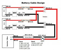
I used 2/0 from batteries to Busbar on the battery paralleling side.So 4/0 from batteries to the busbar and then did you use 2 AWG from the busbar to the secondary 120 MPPT charge controller? Then from the busbar, you connected to the Battery + and - inputs with 4/0? The PV 1 output from the combiner box goes straight to the growatt 12KW and PV 2 output goes to the Secondary 120A charge controller, correct? This is where I am trying to understand what is happening and your diagram is the first time I have seen it on paper and not just reading it in a discussion, so please bear with me.
4/0 from busbar to busbar.
4/0 from busbar to inverter
2 awg from busbar to 2nd SCC.
Our basic battery diagram with a few modes in the end. Not show is the Busbar added after the switch to accomidate the input/out put of the second SCC. Also ended up using 225 amp class T fuses and not the 400 amp ones
The 12kw Growatt says 3*2AWG, did you do that or just use another sized wire?
4/0 is about the same size as 3*2awg
I have an 8-2 combiner box from Watts247. It is probably the same concept as what you have except you use the Anderson plugs and I like that better for quick disconnect, etc.
in my final design, because we ended up with 2 charge controllers, and broke the array down into 8 strings, we went with Two 4 in / 2 out combiners from Watts247. This way we'd end up with 2 PV inputs to each SCC.
Last edited:
MrM1
I'm Here, But I'm Not All There
MrM1
I'm Here, But I'm Not All There
How to build a Pre Charge Resistor Switch from a Boat Battery Switch
My pre charge switch on my home system used for the Conext SW4024
My pre charge switch on my home system used for the Conext SW4024
SniperX
Solar Enthusiast
- Joined
- Apr 1, 2021
- Messages
- 345
I saw this thread earlier. You have some great posts!!! Way over my head, but still, very interesting.How to build a Pre Charge Resistor Switch from a Boat Battery Switch
My pre charge switch on my home system used for the Conext SW4024
SniperX
Solar Enthusiast
- Joined
- Apr 1, 2021
- Messages
- 345
SS told me to use the 400A Class T fuse. I did the calculations and all and came up with around 336A and thought a 350A fuse would be fine but they said to use the 400A Class T fuse. So, to support that, 4/0 would be my choice. What made you decide to go to a 250A Class T fuse?I used 2/0 from batteries to Busbar on the battery paralleling side.
4/0 from busbar to busbar.
4/0 from busbar to inverter
2 awg from busbar to 2nd SCC.
Our basic battery diagram with a few modes in the end. Not show is the Busbar added after the switch to accomidate the input/out put of the second SCC. Also ended up using 225 amp class T fuses and not the 400 amp ones
View attachment 116420
4/0 is about the same size as 3*2awg
in my final design, because we ended up with 2 charge controllers, and broke the array down into 8 strings, we went with Two 4 in / 2 out combiners from Watts247. This way we'd end up with 2 PV inputs to each SCC.
MrM1
I'm Here, But I'm Not All There
I agree with that. But I went with 225 though specifically because no one battery bank that I built will see over 200 and the BMS I installed on each bank can only deliver 200. So if one goes down, I didn't want the other bank to try and provide the full load.SS told me to use the 400A Class T fuse. I did the calculations and all and came up with around 336A and thought a 350A fuse would be fine but they said to use the 400A Class T fuse. So, to support that, 4/0 would be my choice. What made you decide to go to a 250A Class T fuse?
Our plan is to have at least least 4 battery-management-systems-bms banks in the end
SniperX
Solar Enthusiast
- Joined
- Apr 1, 2021
- Messages
- 345
Makes sense. Thank you for sharing your setup and knowledge. Still pondering the PV side of things on the diagram and the photo. The battery cables go from the switch to the positive and negative busbars, then from there, a positive and negative cable goes to the second charge controller, AND from the same busbar, another positive/negative cable goes to the Growatt 12kw. The 2 PV strings (say string 3 and 4 out of 4) go from the combiner box to the second Charge controller and strings 1 & 2 go from the combiner box to the Growatt 12KW? Do I have that correct? What size Anderson Plug are you using? 50A? I am assuming this due to the connection plate you wired into the combiner box...but I could be wrong.I agree with that. But I went with 225 though specifically because no one battery bank that I built will see over 200 and the BMS I installed on each bank can only deliver 200. So if one goes down, I didn't want the other bank to try and provide the full load.
Our plan is to have at least least 4 battery-management-systems-bms banks in the end
Similar threads
- Replies
- 8
- Views
- 617
- Replies
- 8
- Views
- 496
- Replies
- 83
- Views
- 6K
- Replies
- 23
- Views
- 1K


