diy solar

diy solar

Adding Schneider XW Pro

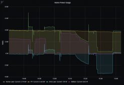
I have it set to stop charging the battery at 4:00, I don't really know why it stopped charging after the AC kicked on for the first time at roughly 3:30. Those huge wattage spikes are the central AC cycling on and off.

Maybe something to do with bulk/absorption/float if it has those concepts? If it was in the middle of absorption and all PV diverted to A/C, might it think tail current tailed off and switch to float voltage which wouldn't take any more current? How full was battery? Does it also draw from grid to charge battery, or only from PV?

You stop charging at 4:00 - is that for peak utility rate time? Do you also have 3:00 part-peak?
 
It had just transitioned from bulk to absorb (@3:13), but it doesn't look like it finished the absorb cycle.
I had been doing this control manually on and off for a few weeks and I feel like I surely would have turned down the charge for the AC to run during absorption, but maybe not.

But, considering it just transitioned to absorb the battery was full enough for my purposes.

I am also fairly certain I have float turned off.

To answer your question on where it draws current to charge the battery. My PV is AC coupled, Schneider isn't smart enough/couldn't be bothered to program in the logic to do anything like a grid zero or similar implementation where it adjusts charge current depending on grid usage. If you tell it to charge at X, it will charge at X and pull it from anywhere. The way electricity works, it would come from PV first then from the grid.

1626360444903.png

Yes, I stop charging at 4:00 because that is when peak starts, and no we do not have a partial peak.
 
Float off - does that mean it holds absorption voltage forever, doesn't drop to a lower float voltage? Or does it just turn off battery charger in which case battery is essentially disconnected rather than held at a float voltage, drops to a settled voltage?

Do you have battery voltage log, see if there was a transition when charging stopped?

That is my guess - because it suddenly started drawing current from battery with the right hand, the left hand though tail current went away. Are these completely independent charge and discharge circuit? Or more likely a bidirectional inverter, so the same inductor and transistor is either charging or discharging?

AC coupled, so like my Sunny Island AC power is AC power. Although, there is a current sensor on grid connection and disconnect relay, and it does comprehend whether current is being drawn from grid while charging and has a separate limit on that. It can't know what is happening between GT PV and loads, but it can distinguish surplus PV charging battery vs. grid feeding loads and/or battery.

"Full enough" of course differs from full to a particular level. Once LiFePO4 transitions from CC to CV, it continues to charge. I'm not sure what percentage remains, but I hear that too long as some relatively low voltage can reach the more damaging 100% SoC. I would guess anything at or above the voltage a 100% charged cell settles to would do that. Some target like 95% should be an upper limit (unless it will immediately start discharging.)
 
On the Schneider XW-Pro, the "No Float" charge mode drops to essentially zero current at the end of the absorption cycle.

The basic XW-Pro does not have external current sensors. It does measure the current coming in the grid AC1 input and the inverter output, so it can self adjust to adjust the inverter power to hit a target AC input current, but if you have any loads back at the main panel, it has no idea how much power they are using. I have mine set to send 3.5 amps back to my main panel curing the peak time of use rate 4pm to 9pm. That more than covers my normal loads, but not when my air conditioning turns on. So I know I have to buy some power to run the A/C with this setup. The XW-Pro does handle loads on it's output very well. It will adjust the inverter current to always cover the output loads. After 9 pm, when we go to the lower cost electric rate, I have it only power the output side loads, and the main panel just runs off the grid. This basically uses up the rest of my solar power that I stored during the day, without selling it at the cheap rate back to SCE.

The charge side is just dumb, as 400bird pointed out. Currently, I have mine just charge at a fixed power from about 9 am to 3 pm. In most cases, it is less power than my solar is producing. If the A/C is not running, I do see up to 1,100 watts going out to the grid. But when the A/C does kick in, I am pulling 2,000 watts from the grid. Ideally, it would be best to monitor the grid power, and adjust the charge current to try and keep grid power near zero.

There is an option to add a "Watt-Node" box that measures the grid power at the main panel. The XW-Pro does have software built in to adjust the grid sell current to zero the grid export. That would raise and lower the inverter current automatically when the A/C starts or other loads back in the main panel. But it still does not adjust charge current. 400bird and I are both looking at using an external controller to add these functions. He is further along, and his progress looks great. These would all be easy things for Schneider to add to the Gateway and just have it handle the control, but they just don't seem interested in helping out AC coupled systems. They want us to add one of their MPPT charge controllers to do all of the battery charging.
 
It had just transitioned from bulk to absorb (@3:13), but it doesn't look like it finished the absorb cycle.
I had been doing this control manually on and off for a few weeks and I feel like I surely would have turned down the charge for the AC to run during absorption, but maybe not.

But, considering it just transitioned to absorb the battery was full enough for my purposes.

I am also fairly certain I have float turned off.

To answer your question on where it draws current to charge the battery. My PV is AC coupled, Schneider isn't smart enough/couldn't be bothered to program in the logic to do anything like a grid zero or similar implementation where it adjusts charge current depending on grid usage. If you tell it to charge at X, it will charge at X and pull it from anywhere. The way electricity works, it would come from PV first then from the grid.

View attachment 56355

Yes, I stop charging at 4:00 because that is when peak starts, and no we do not have a partial peak.
It sure looks like you are making much better progress than I am on external control of the XW-Pro. I have not worked with a Raspberry Pi at all yet. Would you be interested in setting up another one and helping me configure it for my system? Obviously, I would help fund your development. Each time I think I get a step closer with my setup, I run into another issue.
 
I had no experience with the Raspberry Pi either. But the good news is they're not expensive. I figured if I didn't get it worked out it wasn't a huge loss.

I have a raspberry pi 4 running rpi-power-monitor

I also purchased the board and components from the author of that software, he's got a link somewhere in there too, plus I believe I already posted it earlier.

Mostly my setup is all based around that power monitor software and 3 current sensors, I think I added maybe 30 lines of python code. I have very little python (or any coding) experience, but I made slow progress and have a functioning first step.
I will gladly share my few lines and do my best to get you set up. Maybe we can figure out better tuning to avoid the over reaction my system has the the PWM of the stove...

I also have mqtt installed and sending the charge command to node-red. Node red is sending it out over modbus tcp.

I would like to get the power monitor program to talk directly to the XW over modbus, not through node-red. I am sure it is possible, but I haven't even started researching that yet. Hoping to start into that next week as I work through sending force bulk command.
 
Ok, I figured out a temporary solution to command bulk charge to start in the morning.

In node-red it's pretty easy to set up a timer to send a command at a specific time. But, I don't know how or if it is even possible to have it wait and retry if it fails to communicate with the XW.

My problem was that the XW modbus need to be woken up prior to accepting any commands.

My temporary solution is to read the "command bulk charge" register every 5 seconds. All day, all night. Not elegant, but it does mean that when I command bulk charge at 8:00 am the modbus node/address is alive and ready to accept commands.

So, that means that today the system acted somewhat as it should have out of the box. It started charging after production exceeded demand and only charged using excess PV production.
 
Excellent work.
It makes no sense at all that Schneider won't build that function into the system, but it sounds like you are getting pretty close to wrapping this up.
 
I've got to just keep going, one step at a time. At the beginning it felt like it was staring at a mountain I'd never climb...
Thanks for the encouragement.

Turns out I'm polling the charge command every 10 seconds.


If you decide you want to try out this solution, I'll happily share my progress. I'm no coding expert and I didn't stay in a Holiday Inn last night, so I'm sure there's tons of room for improvement.
 
Maybe something to do with bulk/absorption/float if it has those concepts? If it was in the middle of absorption and all PV diverted to A/C, might it think tail current tailed off and switch to float voltage which wouldn't take any more current? How full was battery?

I just finally spent some more time on this today. Yes, it appears you are correct.

Once the XW switches to absorption charging, if continue to follow my current programming and the AC kicks on in the afternoon I end up pulling something like 60 watts from the grid and command the charger to 1 watt. The charger can't actually charge at 1 watt, but it keeps the bulk charge program going. When the AC cycles off and charge command picks up, the bulk charge continues, it does not with absorption charging.

The easy route is to try something slightly higher for my minimum charge command, I am going to try 10 watts and see what happens. This is still below the minimum threshold that the XW can output, but maybe it will keep the absorption charge program alive?

Otherwise, I will either need to build in more logic to restart the charge command. Or, I can just add some small DC coupled solar as I have been toying with in my head. Then the MPPT charge controller can handle absorption.
 
Slow progress here, still toying with adding a few more panels and a small MPPT charge controller.

But, I still have to finish assembling my battery!
I tried a few temporary things to keep the battery cool, but I am not excited to blow air and dirt into the battery box. Or replace filters on some sort of maintenance schedule.

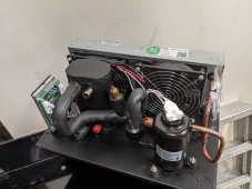
So, in my infinite desire for new toys, I purchased a small chiller to cool the battery.

PXL_20210915_055231521.jpg

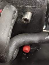
I went through the specs pretty thoroughly with the vendor. But, I missed one important issue. How they connect the cooling hoses to the chiller! They just have blank, unthreaded 12mm diameter boss sticking out!? I can't call them pipes because, well look at that wall thickness.

PXL_20210915_055242387.jpg

6.5mm ID, 12mm OD

When I brought this up to the vendor, they recommended just slapping a hose and hose clamp on it!
In my experience you need some sort of mechanical retention so it doesn't slide off. Such as barbs or whatever you call the flared bump on the end of an intercooler pipe or radiator fitting.

I thought about drilling at tapping for a 1/8" NPT fitting. That would leave me with less than than 2mm wall thickness.
I haven't found a size that works for the outside of the boss to thread male threads. Also, the refrigerant lines are close enough to cause some difficulty spinning the die.

I think the best option is to solder 1/4 copper pipe into the bosses on the chiller. Then I can properly transition that to soft hose with a compression fitting or bubble gum with a side of hopes and dreams. Lol

Or am I overthinking it and should I trust the friction of a 1/2" hose with a hose clamp on a 12mm boss?
 
I have on idea, but it may sound a little crazy.

I think you had a lathe, right? Machine a threaded fitting or hose barb with an i.d. so it is a snug fit around the 12 mm o.d. of those bosses. Then use a retaining compound something like this
With just a reasonable close fit, it will seal and bond it on without having to subject the fitting to any heat or stress. I have used a few retaining compounds like this to hold bearings on shafts and keep bushings from walking out.
 
I like the idea of having dedicated cooling. A couple questions for you how is the boss attached to the chiller (?) hiding underneath the black insulation? Also, am I right that this connection is for coolant rather than refrigerant - i.e. you won't have the refrigerant going through this connection, correct? If it is a refrigerant line and if I have understood GXMnow's solution (EDIT: reading through it again, I'm not sure I did), you could use Nylog - there's a 'blue' and a 'red' - you have to get the right one for your refrigerant - it's the oil/sealant that HVAC installers use at compression fittings and is compatible with the compressor oil.
 
I can't tell the material, is it steel or aluminum?
Before heating it (solder idea), look under the black insulation to determine how the pipe is connected to the assembly.
It might be crimped, or soldered.
If crimped, consider the torque the crimp will be subjected to if tapping the pipe vs soldering.
If soldered, you might want to heat sink the pipe to keep the solder from melting when the open end is heated.
Do you have a die grinder & small carbide burr?
If so, the hose & clamp idea is OK, just cut one or two shallow grooves around the exterior of the pipe, so as to give the hose ID somehting mechanical to bite into
 
I have on idea, but it may sound a little crazy.

I think you had a lathe, right? Machine a threaded fitting or hose barb with an i.d. so it is a snug fit around the 12 mm o.d. of those bosses. Then use a retaining compound something like this
With just a reasonable close fit, it will seal and bond it on without having to subject the fitting to any heat or stress. I have used a few retaining compounds like this to hold bearings on shafts and keep bushings from walking out.

I don't have a lathe, but for an operation that simple, I might just see if I can find a threaded fitting that will drill (or ream) out 12mm.

Is that bearing retainer water tight? I should just read the data sheet myself.
 
I like the idea of having dedicated cooling. A couple questions for you how is the boss attached to the chiller (?) hiding underneath the black insulation? Also, am I right that this connection is for coolant rather than refrigerant - i.e. you won't have the refrigerant going through this connection, correct? If it is a refrigerant line and if I have understood GXMnow's solution (EDIT: reading through it again, I'm not sure I did), you could use Nylog - there's a 'blue' and a 'red' - you have to get the right one for your refrigerant - it's the oil/sealant that HVAC installers use at compression fittings and is compatible with the compressor oil.

Refrigerant goes through the lines under the insulation on the left. The exposed ports are for coolant (water, well mostly water, I'm going to use automotive coolant)

Yes the there is a small plate chiller under that insulation. I'll have to open up the insulation some to check how the boss is attached.
 
The boss is soldered on
It is not magnetic
No color under the silver, so it's not coated copper.
Seems harder (more scratch resistant) than the aluminum I have available (6061)

I still think it's probably aluminum, but it might be stainless.


I think I'm going to modify GXMnow's idea.

I'll either drill or ream out an appropriate sized threaded female fitting. Likely 1/4 npt, as the major diameter is roughly 13mm, minor is 11. So when I open it up to 12, there will still be all of the original strength.

I'll need to add some mechanical grip on the boss for the retaining compound, like PVdude said, die grinder and carbide bit.

I think I'll need to switch from a bearing retainer to an epoxy, because I'm not going to be able to tightly control the clearance between the fitting and the boss.
 
Loctite has several different compounds. Some will fill more gap than others. The better the fit, the thinner the solution needed. A basic epoxy will probably work just fine as well. With the retaining solution, you would really only need to scuff the outside of the boss with sandpaper to have it grip tight. I do have a lathe here, but it is what, 300 miles to machine a part?
 
My concern with drilling out a NPT fitting is that there will still be about half of the threads remaining. So it won't have surface area most of those compounds are designed to hold. Hence my thought of adding something mechanical on the boss and using epoxy.

I do like the lathe idea. It isn't a 300 mile drive, it's just one FedEx shipment away if you're willing. I'll pay.
 
Refrigerant goes through the lines under the insulation on the left. The exposed ports are for coolant (water, well mostly water, I'm going to use automotive coolant)

Yes the there is a small plate chiller under that insulation. I'll have to open up the insulation some to check how the boss is attached.
OK, understood. In that case, why not just run a test with a hose and hose clamp to see if you get any leaks? I like PVDude's suggestion of adding "one or two shallow grooves around the exterior of the pipe, so as to give the hose ID somehting mechanical to bite into." Do you have a spec for the pressure on this side of the system? If this is the cold side of the system, my guess is that the pressure is low enough to allow this to be an effective solution.
 
Back
Top