MT off grid
New Member
- Joined
- Jan 23, 2022
- Messages
- 571
If the wiring is sized correctly. It can be done safely.
And there's no code that says two loads can't share the same feed.


If the wiring is sized correctly. It can be done safely.
And there's no code that says two loads can't share the same feed.
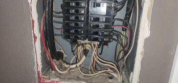
The terminals on that receptacle are not rated for multiple conductors. You will have to make joints in the box. Or in a separate box, so that your not cramming everything in one box.So would I just use a romex clamp on each leg or would it need to be ran through conduit? Also are two conductor ls allowed in each screw clamp (lack of actual name) on the back of the socket or is there another way I would split off each leg?
The terminals on that receptacle are not rated for multiple conductors. You will have to make joints in the box. Or in a separate box, so that your not cramming everything in one box.
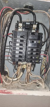
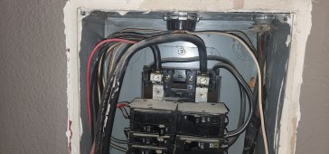
Another option is to use that feeder to feed a small (4 circuit) sub panel. Put a 30a two pole breaker in it to feed the dryer and the other two spots can feed the inverters.
Yes, but you still have to not run both at the same time.I like that idea, so the double poll feeding the outlet now would be the main breaker that feeds the sub-panel? The existing breaker is a double pill 30 now so is it okay to feed a sub-panel with a double poll 30 that then split into another double poll 30 plus two additional 15 amp singles?
Yes, but you still have to not run both at the same time.
Yes, but you still have to not run both at the same time.
This just tells me that they're not very experienced.
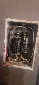
Any time I was asked to add a generator input to a house panel. I was very happy to see a split buss panel. Because it made everything easier.
A split buss panel is like having a sub panel already built in.
If it was an outdoor panel, even better.
An outdoor split buss panel meant that it was only going to be about a half hour long job. I would show up with the inlet receptacle already mounted and wired into the transfer switch. Along with the nipple and wiring for the panel. Drill one hole in the panel, mount the transfer switch, and connect the 6 wires.

You are absolutely correct. My mistake.
That's a dangerous animal You have there.
But, if it's now a sub panel from the garage panel.
I would just replace the whole panel.
The newer backup panels are designed with a split buss setup and interlock included. Makes it really nice for a generator or inverter backup system.